

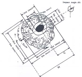
Each impact observed during the post-flight analysis is measured and several parameters are stored in the database. The main parameters are described following (see figure).
Front Top: a central pit (Dp); a region of shatter immediately outside this (Ds); a conchoidal fracture zone beyond this (Dco); an outermost area of irregular damage (Dm).
Front Back: a central pit (Dp), in some cases the RTV adhesive is exposed (Drtv), regions of inner and outer spall (Dis and Dos) and a large area of variable damage (Dm).
Rear Top and Back: a central hole (Dh) and an extended burned area (Dl).
Scale: S is the spacing in mm of the silver wire grid on the cell side or the space between two meshes on the back side to be converted in SI units.
Magnification: Z is the zoom factor of the microscope obtained with dividing the scale factor by 1.25 for cell side or 0.35 for the rear side.
Engineering units: real dimensions in mm.
Cracks n°: number of clear cracks present in a given feature.
Spall n°: number of spall presents in a feature particularly on FB impacts type A or B
Angle: In the case of FT non-circular impacts it is possible to determine the impact direction, q is defined as the angle anticlockwise from the vector X parallel to the grid and the velocity vector V in the direction of impact.
Ellipticity:
- C is the position of the pit centroid relative to the spallation diameter;
- M is the mean impact diameter,
- Da is the along axis of the pit (parallel to the direction of approach of impactor),
- Db is the cross axis of the pit (generally Da>Db excepted for butterfly features),
- S is the scale factor,
- Z is the magnification.
It is noted that if the impact feature of any feature is elliptical, the minimum and the maximum diameters are recorded in the same Excel cell separated by "/".