

Overview:
One of the two Solar Panel Assembly (SPA) wings of Hubble Space Telescope (HST) was retrieved after about 3.6 years (1.14 x 10 8 seconds) of exposure in the Low Earth Orbit. A detailed microparticulate impact survey of the wing was carried out with CCD photography at ESA/ESTEC in the summer of 1994.
PFA 1
Solar Cell Analysis:
The physical layout of the wing is shown in Figure 1, with the main telescope body in the centre, and the two solar array wings on either side, both wings were rotatable about the attachment axis to the telescope body.

Figure 1 - Solar Array Configuration |
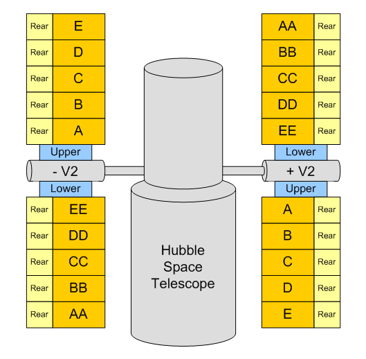
HST Schematic Build-Up |
|
During the Hubble repair mission which occurred in December 1993, one of the wings (the +V 2 wing) was found to have damage to one of the bi-stem booms, preventing it from being rolled-up into its cassette for subsequent removal and stowage in the Orbiter. Due to the severe time constraints on the HST repair mission and the importance of the repair of the telescope optics, the damaged wing was released by one of the astronauts to burn-up in the atmosphere.
The other wing (-V 2 wing) was recovered safely however, and returned to the ground for post-flight analysis.
The -V 2 wing consists of two separate blankets on which the solar cells are fixed, denoted as the "upper" and "lower" blanket respectively. There is a cassette in the centre to which these two blankets are joined, and into which they can be retracted in the same way that a film is retracted into a film cassette. The retraction must be performed in a certain way so as not to damage the solar cells which are only attached to one side of the blanket.
The side view shown on the left of Figure 1, shows the retraction/deployment configuration and explains the reason for the terms "upper" and "lower". When the blankets are laid out horizontally, one blanket is higher than the other due to this retraction/deployment mechanism.
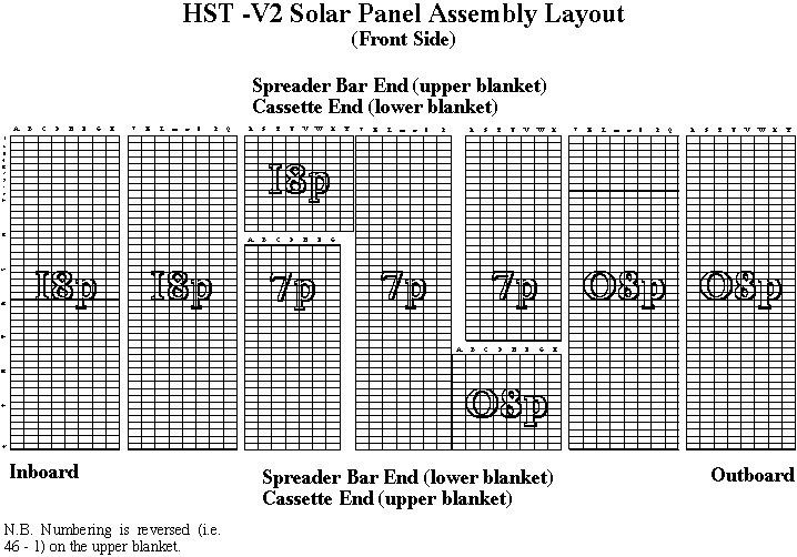
Figure 2 - Solar Panel Assembly Layout
There is a spreader bar at the end of each of the blankets to which is connected the two bi-stem booms which provide the blanket support (the spreader bar is furthest away from the cassette).
Each blanket is made up of seven individual segments joined together. There are 5 Solar Panel Assemblies (SPAs), with a buffer assembly on either side, the inner and outer buffer assemblies respectively (the inner buffer is closest to the cassette and the outer buffer to the spreader bar).
Each of the SPAs and buffer assemblies have unique identification numbers marked on them, but are identified for convenience as A-E and AA-EE for the upper and lower blankets respectively in the rest of this report.
The physical layout of the solar cells on each of the SPAs is shown in Figure 2. The cross section of an individual solar cell, consisting of a multiple layer structure of various materials, is also shown in Figure 3.
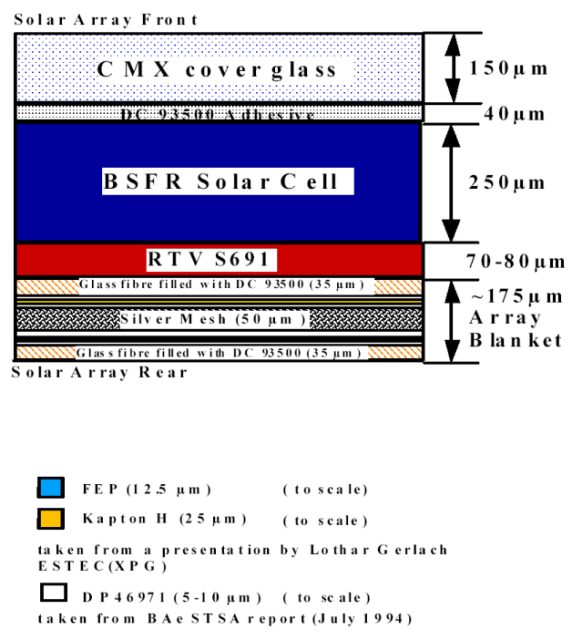
Figure 3 - Solar Array Materials
Here you can find the images of post-flight-analysis 1.
Residue Analysis:
The main findings of the survey can be summarised as follows:
- Impact features are readily observed in both solar cells and buffer assembly material.
- Seven out of twenty primary impacts (35%) completely penetrated the solar cells. All five of the impacts into the buffer assembly completely penetrated the material.
- Chemical analysis of the solar cells and the buffer assembly identified their main constituents as Si plus minor Ca, Al and Mg, with additional Ce ± Zn in the solar cells and Fe in the buffer assembly.
- Abundant material foreign to the solar cells and buffer assembly were identified by analytical SEM. However, all the material found was deemed to be contamination: from rocket propellant, paint fragments and salt particles.
- Only one impact (sample S65) might possibly be from a natural micrometeoroid, but even this is doubtful.
- At least three holes show evidence for different impactors, attesting to the complexity of the impact process.
PFA2
The second set of HST solar arrays has provided another unique opportunity to measure the meteoroid and debris environment. The arrays provide (because two were retrieved rather than one earlier) 8 times the area x time product of the first array and could extend the measurements of the larger particle sizes. The impact analysis also provides information on potential changes in the space debris environment.
The HST Solar Arrays have been deployed by the Space Shuttle Endevour on Decembber 4th 1993 (STS61) and has been retrived by Space Shuttle Columbia on March 3rd 2002 (STS109) from this the following Mission Exposure times result:
| Lapsed Days | Years | Seconds |
| 3011.00 | 8.24 | 2.601504 x 10 ^8 |
Here you can find the images of post-flight-analysis 2.