
Empirically developed equations provide simplified descriptions of the damage caused by impact. There are three different sets of equations which cover the three different thickness regimes: semi-infinite thickness equations for craters, marginal thickness equations for marginal perforations and finite thickness equations for perforations.
Many empirical and semi-empirical relationships have been developed to convert crater morphology to particle mass or diameter, equivalent crater size in aluminium or equivalent penetration thickness. Typical target/impactor regimes for which specific damage equations have been developed include:
- P/d equations for semi-infinite targets: These were developed mainly for shielding where the crater depth P was considered the most important parameter as in the ballistic limit. The ratio P/D, for crater diameter D is generally assumed to be equal to 0.5.
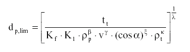
- Marginal thickness f/d equations: Instead of crater depth, the critical parameter is the target thickness f at marginal perforation.
- Finite D/d equations
- Equations on glass:
Few empirical equations have been developed from previous calibration shots. The velocity exponent of value 2/3 assumed by several authors derives from the assumption that the volume of mass ejected from a crater is proportional to the kinetic energy of the particle that caused it. Five authors have attempted the construction of equations:
- McHugh and Richardson (1968) on semi-infinite glass targets.
- Gault, Hörz and Hartung (1972) for lunar rock (i.e. on basalt and granite).
- Fechtig (1974) adapted from Gault’s lunar rock equations to find a formula for ‘conchoidal cracking’ or spall diameter ( mm to cm size range).
- Cour-Palais (1982) MSC Apollo window damage equation.
- Paul and Berthoud (1995) they used the Fechtig equation as a base for Dco and Dpit equations, comparing it to a much wider dataset and adding a ‘cosq’ term.
- Updated semi-infinite equation on glass (1996)
- Equation for HST finite data (1996): Resulted from a multi-parameter least squares regression on the HST finite data.
- Calibration equation for EURECA and HST:
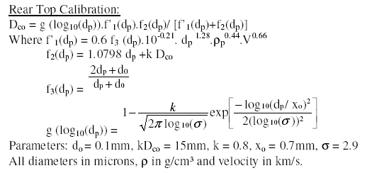
Calibration curves relating impacting particle diameter and resulting late spallation/brittle fracture damage feature diameter have been obtained, in previous contracts, for penetrating and non penetrating impacts on both the front and rear sides of the HST solar array (McDonnell et al, 1998). These were derived from hypervelocity tests on solar cell and from data obtained after EURECA and HST post-flight analysis. These equations appear to be valid at both light gas gun and mean meteoroid impact velocities. The HST front top calibration equation also applies to the front surface impacts detected on the EURECA spacecraft.
Using these equations the incident fluxes on the HST and EURECA (front side) solar arrays have been converted to particle diameter distributions (assuming average meteoroid impact velocities). One damage equation was derived per type of impact. The main input parameters for these equations are:
- Specific diameter for each type of features
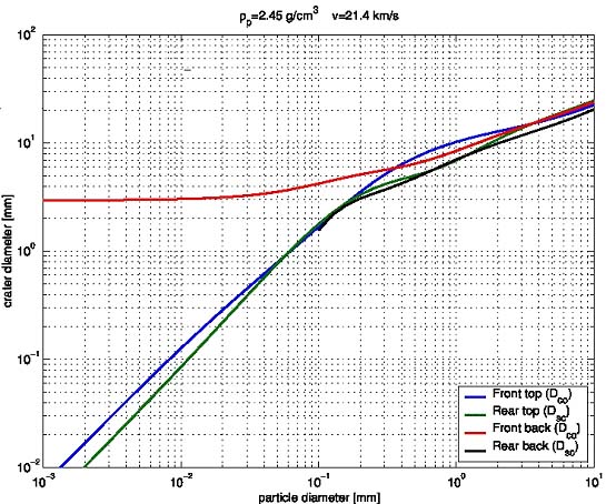
- Mean velocity: v =10km/s for Space Debris, v = 21.4km/s for Meteoroids
- Mean density: r= 4g/cm3 for SD, 2.5g/cm3 for MM
The output is the particle diameter. The following figure gives an example of conversion curves with the assumption that the projectile is a meteoroid. You can find detailed equations below, they are also given in HST PFA2 TN4 (Appendix B).