The default geometry is a single planar slab geometry with 26 layers (the boundaries are equivalent to the default SHIELDOSE [R16] thicknesses, but the geometry as a whole isn’t). The material for the default geometry is Aluminium.
The default geometry shape is planar slab.
It is mandatory to issue the command /geometry/update after any changes to the geometry setup to apply the changes.
Note
layer thicknesses less than an equivalent of 10 microns of Silicon or Aluminium are not recommended for nonMC analyses.
The command to add a new layer is /geometry/layer/add. It takes 5 parameters in the same line:
position - integer denoting after which layer the new layer will be inserted
material - name of the material for the layer
colourindex - number of the colour used to visualise the layer (see Geometry colours)
thickness - layer thickness in terms of units
unit - unit of the thickness.
Use 0 as the layer number to insert the first layer.
In the example below, using a spherical geometry, an Aluminium and a Silicon layer are created first, then a layer of Air is inserted between the Aluminium and Silicon layers, i.e., after layer 1.
The shells in a spherical geometry configuration are defined the same way as the layers in planar geometry. A couple of points should be noted however:
The first layer is the outer-most shell.
The last shell, i.e., the inner most one, is a solid sphere.
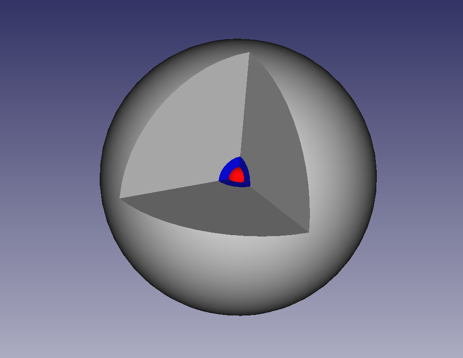
So the same commands in the example above will initially create a solid silicon sphere with a radius of 1 mm surrounded by an Aluminium shell 1 cm thick, then with the addition of the Air layer, the geometry will have a 1 mm air “gap” between the Silicon and Aluminium layers.
This figure shows the above geometry, consisting of a 1 cm outer layer of Aluminium (grey), a 1 mm inner layer of Air (blue), and a 1 mm radius inner sphere of silicon (red).