

EURECA MLI Reports
EURECA Thermal Blanket Investigation (EWP 1825)
ESTEC WORKING PAPER (EWP) No. 1825
by
Lucinda Berthoud
Environmental Effects Section
Materials & Processes Division
Table of Contents
- Introduction
- Description of Samples
- Sample Preparation Procedure
- EDX Analysis
- Results
- Further Activities
- Conclusions
- References
- Figures
- Spectra
Introduction
The space platform EURECA (EUropean REtrievable CArrier) spent 11 months in a sun-pointing orbit at approx. 500 km altitude and 28.5 degree inclination. It was recovered by the Shuttle mission STS-57 on the 24th June 1993. The surfaces of the retrieved EURECA provide useful information on the near-Earth particulate environment. The recovery of spacecraft materials peppered by particle impacts provide an unprecedented opportunity to investigate various aspects of meteoroid and debris flux in low-Earth orbit (LEO). Figure 1 shows the spacecraft and its orientation axes (see reference Unispace Kent/SAS/Maag/MC/CERT (1994)).
Multi-Layer-Insulation (MLI) blankets covered most of the spacecraft for thermal control purposes (see figure 2 from Kelley and Martino, 1989). It was realised early on that the multiple layers of these blankets could act as a thin film collecting device, slowing down and breaking up impact particles as they penetrate the layers. It was hoped that residues of the impact particles would remain on some of the layers. These could then be chemically analysed in order to deduce the origin of the impactor. The multiple film method is a recognised way of collecting particles, but so far no investigations of impacts into MLI have been carried out. It is hoped that this work, together with concurrent investigations at the Open University, GB, will shed some light on particle origins and hypervelocity particle damage to MLI.
Description of Samples
Three samples with impacts were cut from two different types of MLI blanket attached to the spacecraft. The two different blankets were Type 6 MLI and a plume impingement shield. The samples suffered a certain amount of handling in their transfer from Kennedy Space Center to DASA Bremen and then to the Open University, GB where they were photographed and sent on to ESA/ESTEC, the Netherlands where this work was carried out. The composition and orientation of the blankets were as follows:
The Type 6 MLI (figure 3) was composed of a top layer of betacloth (Teflon-coated fibreglass woven cloth), then a light block layer consisting of 75 µm Kapton coated on one side with a 1000 * thick layer of aluminium protected against corrosion by an acrylic overcoat of 2000-4000 * thickness ('single-aluminised Kapton'). Then 19 reflective layers follow. They consist of 7.5 µm thick Kapton coated on both sides with aluminium with an acrylic overcoat ('double-aluminised Kapton'), these are separated by 20 layers of Dacron net which act as spacers. All layers are perforated in order to allow outgassing products to escape. The bottom or 'internal' layer consists of 50 µm of Kapton coated with aluminium and a layer of black Electrodag 501 paint.
Two square metres of plume impingement shields (figure 4) were positioned on the corner of the radiator to protect the equipment from ejecta from the thrusters. The shields are composed of 5 layers of single-aluminised Kapton. The top (or space-facing) two layers are coated with white paint PSG-120-FD on the aluminium side.
EU-119.db2.1
This impact occurred on a piece of Type 6 MLI placed on top of the spacecraft on the -X side.
EU-143.g2.1
This impact occurred on a piece of Type 6 MLI. The blanket was mounted on the +Z side of the spacecraft.
EU-293.ac0.2
This impact occurred on a plume impingement shield mounted on the -X side of the spacecraft.
Sample Preparation Procedure
The samples were cut from the MLI covering EURECA as 10 x 10 cm pieces. However, these were too large to fit into the SEM chamber. They were stapled with copper staples to hold the layers together, and were then cut with sharp scissors to 1 x 2 cm samples. The orientation of the blanket was conserved by careful notation. The layers were removed and photographed one by one using a video microscope. Care was taken not to let any loose particles escape, although it is likely that these would already have disappeared during transport and previous handling. Where the surface was one that would charge (beta-cloth, 75 µm Kapton, acrylic overcoat) the samples were sputtered with a 0.5 to 1 µm-thick coating of gold. This was not necessary for the 7.5 µm Kapton reflector layers. The impact damage was examined under the SEM in secondary electron and back scattering modes at different magnifications.
EDX Analysis
Energy Dispersive X-ray analysis (EDX) was performed using a Link AN10000 EDX system in conjunction with the Cambridge SEM. An open window was used with the elemental analysis so that elements including and above carbon in atomic number could be detected. In general, an electron beam of 20 KV was used but where particular elements were being investigated, higher or lower energies were applied.
The analysis was complicated by the variety of materials which made up the blanket. At present all the analyses have been carried out on the top or 'space-facing' surfaces of the layers.
In order to have reference spectra of each surface being investigated, an analysis of an area outside the impact zone was always analysed. The following elements were found to be detectable by our EDX at 20 KV in the various layers (the Au is the sputtered layer added for conductivity and therefore shown in brackets):
- Teflon top of betacloth: F, Si, Ca, O, C (Au)
- Glass fibre part of betacloth: Si, Al, Ca, Mg, O (Au)
- 75 µm single aluminised Kapton: C, O (Au)
- 7.5 µm double aluminised Kapton: C, O, Al
- Dacron net: C, O (diameter of strands is approx. 15 µm and they charge)
- White paint PSG-120-FD: Si, Zn, O, (Au)
A swift analysis of some contaminants on MLI surfaces reveals organic salts (K, Na, Cl, Cu, O, C), bits of stainless steel (Fe, Ni, Cr), paint from the upper layers, strands of Dacron net, bits of shattered Teflon and glass fibres from the Betacloth.
Results
EU-119.db2.1
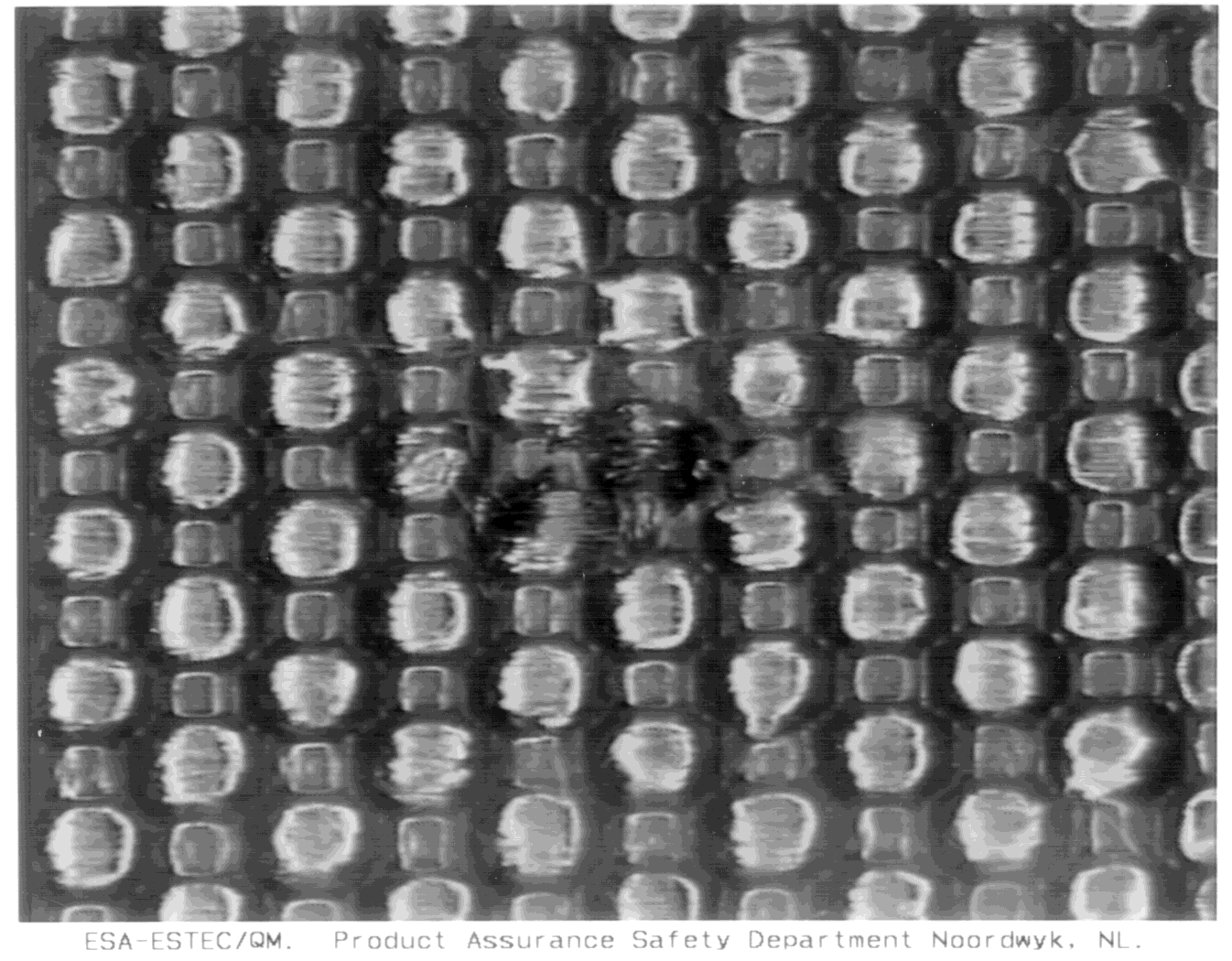
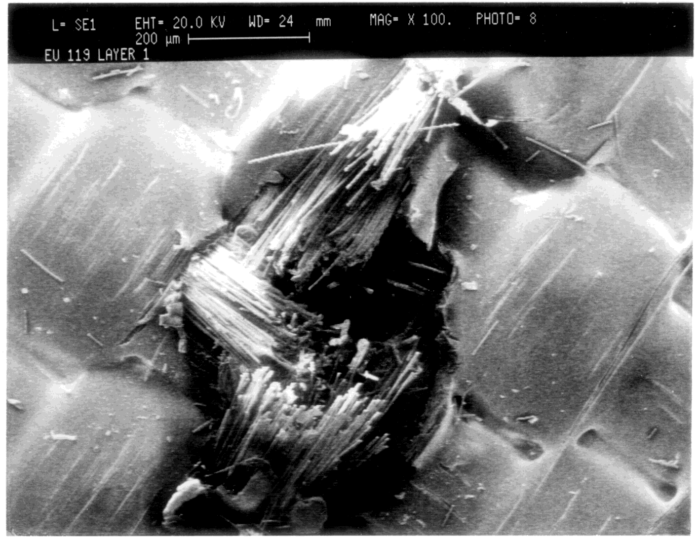
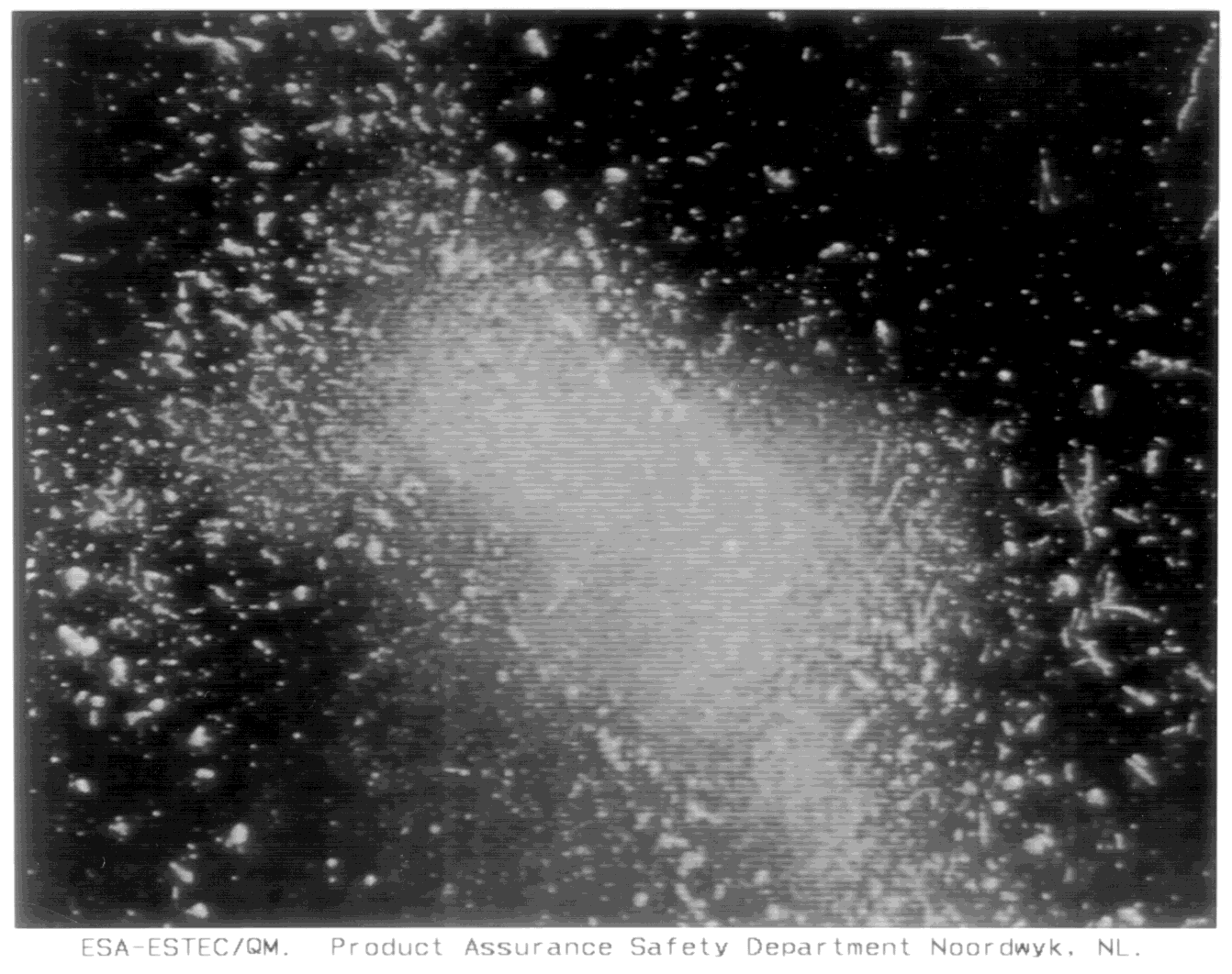
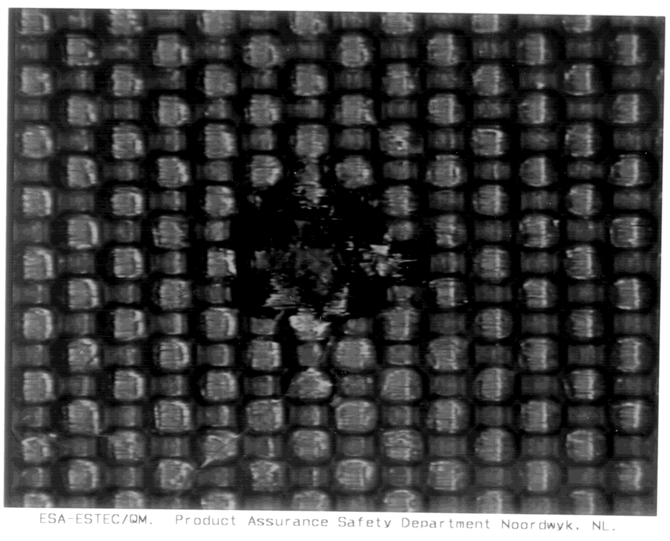
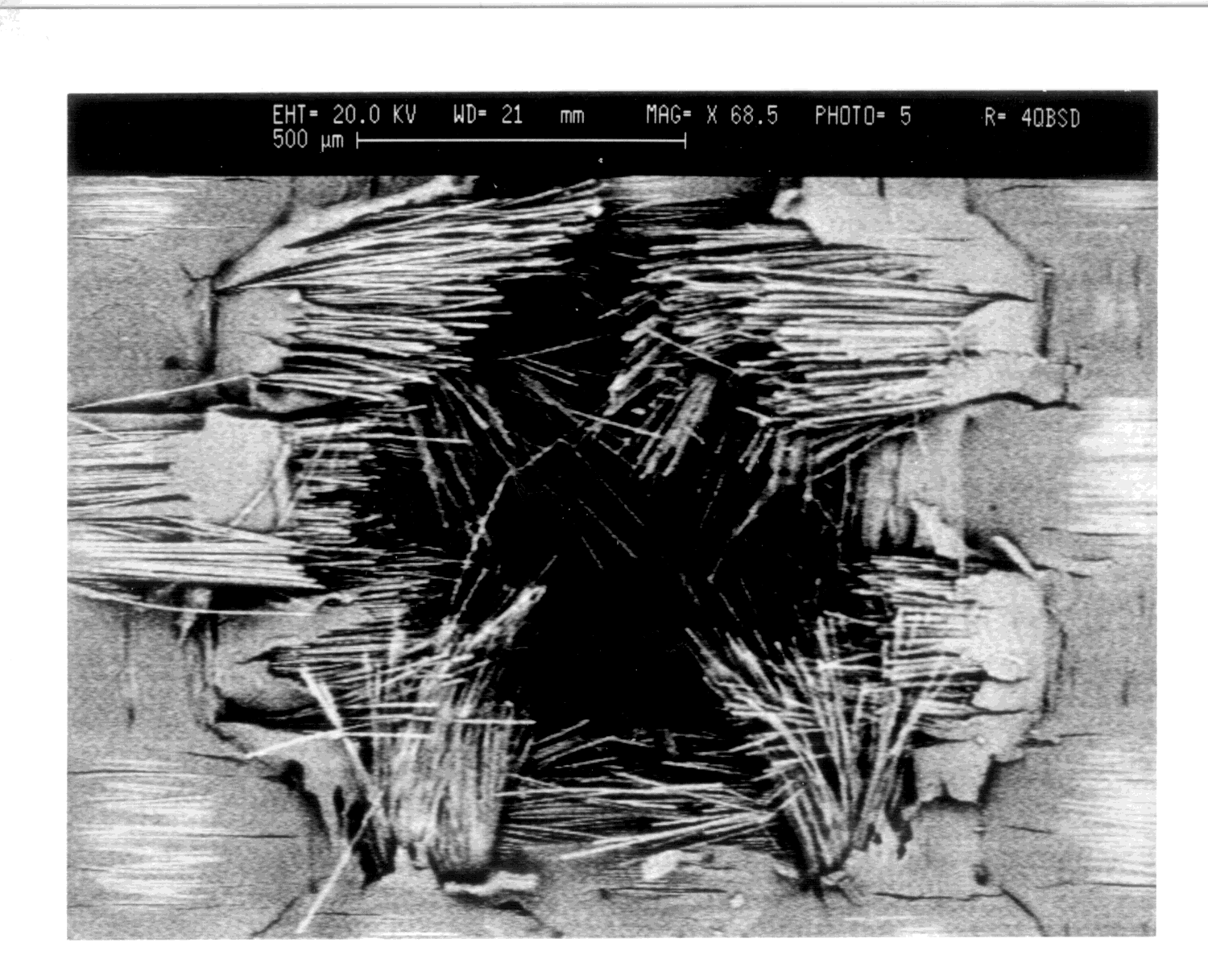
The impact just penetrated the betacloth, leaving a small hole (figure 5 and figure 6). The betacloth was brown in the area of the impact showing the charring effect of high temperature. A close-up of the damaged area shows that the top Teflon layer has shattered in a brittle manner, whilst the fibres show molten ends (figure 7). Glass fibres will often fracture in a clean brittle fashion. But in this case they have melted with the high temperatures and pressures seen during the impact. The projectile was apparently shattered by the impact with this first layer and spread a cloud of particles over the second light block layer (figure 8). These particles seem to have passed through a molten phase, as many are in the form of solidified droplets (figure 9). No physical deformation was apparent on the top of the light block layer, nor on its rear side. No damage was seen on the third aluminised Kapton layer below the light block.
The hole in the betacloth was elliptical, as was the deposit on the light block. This could imply either a rod-like projectile or an oblique impact. However, as the deposits on the light block are spattered in a directional fashion, it seems probable that the impact was oblique.
| Layer Thickness | Material Layer | Long Axis Hole D (mm) | Short Axis Hole D (mm) |
|---|---|---|---|
| 210 um | Betacloth Layer 1 | 0.28 | 0.12 |
| 75 um | Light Block Layer 2 | 4x3 Debris Area | No Hole |
| 7.5 um | Reflective Layer 3 | No Damage |
EDX analysis was carried out on promising looking particles on the glass fibres, but no foreign elements were detected. The fibreglass is not an ideal analysis surface, as even with a sputtered layer of gold, the fibres charge and move (spectrum 1 shows the composition). The next layer with the cloud of deposited debris was thought to offer more promising candidates for residues of the projectile. The only signals detectable came from C, O, and Al, and Au from the sputter coat (spectrum 2). As the top Kapton layer is 75 µm thick, Al cannot be detected through it. It is possible that some Al debris floated into the blanket, although the droplet form seems to preclude this. The signals were not very strong. This may be explained by the layer of deposit being very thin and the droplets being mostly quite small. In order to confirm the possibility of an aluminium impactor, ESCA surface analysis of these droplets would be desirable.
EU-143.g2.1
The impact penetrated the betacloth, the next layer of single aluminised Kapton, and then 8 layers of double aluminised Kapton interspersed with Dacron net. The diameters of the damage were difficult to measure, as the holes in both betacloth and 7.5 µm-thick aluminised Kapton were frequently ragged and irregular.
| Layer Thickness | Material Layer | Long Axis Hole D (mm) | Short Axis Hole D (mm) |
|---|---|---|---|
| 210 um | Betacloth Layer 1 | 1.0 | 0.86 |
| 75 um | Light Block Layer 2 | 1.3 | 1.3 |
| 7.5 um | Reflective Layer 3 | 3.7 | 3.0 |
| 7.5 um | Reflective Layer 4 | 5.1 | 2.8 |
| 7.5 um | Reflective Layer 5 | 2.5 | 2.3 |
| 7.5 um | Reflective Layer 6 | 2.5 | 2.1 |
| 7.5 um | Reflective Layer 7 | 1.6 | 1.5 |
| 7.5 um | Reflective Layer 8 | 1.3 | 1.0 |
| 7.5 um | Reflective Layer 9 | 0.75 | 0.5 |
| 7.5 um | Reflective Layer 10 | 1.1 | 0.4 |
| 7.5 um | Reflective Layer 11 | 0.5 | 0.1 |
| 7.5 um | Reflective Layer 12 | None | None |
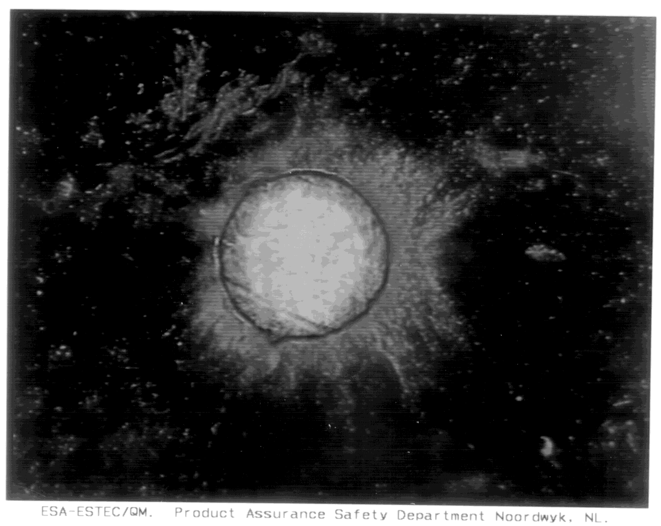
The damage to the betacloth is very similar to that on EU-119.db2.1 (figure 10); the damage zone is highly irregular, with the top layer of Teflon shattered and signs of melting at the ends of the glass fibres (figure 11). The penetration in the light block (single-aluminised Kapton) is almost perfectly circular (figure 12). Kapton does not melt, but chars and decomposes above 800¡C. The edge of the hole looks brownish in the video microscope image showing signs of charring. A fiery halo is also visible around the penetration hole. Close examination of this area shows that this area is littered with residue. The splatters which form the halo are deformations in the surface of the Kapton, apparently caused by the ejection of these residues (figure 13).
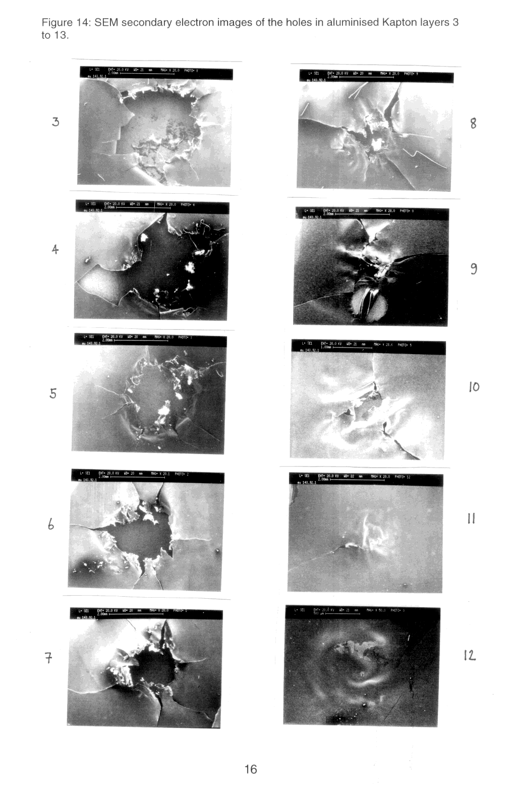
Kapton has a high cut-through resistance and creep strength at high temperatures and a relatively high tearing resistance. However, once a tear has started, it propagates easily under only a light load. The light block layer is considerably thicker than the reflective layers and thus much more resistant to tearing. However, many tears were visible around the impact holes in the reflective layers (figure 14). Although the edges of the holes often appeared charred, the tears in the reflective layers were frequently several millimetres long and were lengthened by handling.
As can be seen from table 3, the largest holes were in layers 3 and 4. Thereafter the size of the holes decreases. Until layer 8, the holes are approximately axi-symmetric, but after they become highly irregular in shape. In all layers there were frequently bits of Dacron net stuck to the edge of the penetration, as it fused with the reflectors at the point of impact. There were increasing amounts of debris around the penetration holes on layers 6,7 and 8.
EDX analysis was performed on layers 1, 2, 4, 6, 7 and 11, as these looked most promising for residues. On layer 1 the area around the hole in the betacloth was analysed, but no foreign elements were found on or around the glass fibres. As already mentioned, it is quite difficult to idenpngy residues on fibres. The splatters around the impact on layer 2 and droplet-like residues showed the presence of Si, O, Ca, Al, Mg, and Au (the gold is from the sputtered layer), whereas outside the impact, analysis shows only O, C and Au (spectrums 3 and 4). The back side of layer 2 revealed nothing in terms of residues. On layer 4, a strong Al signature was found at the edges of the hole. This was clearly due to the acrylic overcoat being destroyed, exposing the aluminium layers. Some strangely-shaped Cu, Cl and Na organic contaminants were also seen. One or two particles around the hole were found to contain O, Ti and Al (spectrum 5). A weak signature of Al, O, Si, S, Ca and Mg was found (spectrum 6). Layer 6 showed little interesting. On layer 7, one particle near the hole was found to contain C, O, F and Al (probably Teflon from the top layer). Particles containing Si, Al, Ca, Ti, Mg, O were also found (spectrum 7). Layer 11 is the layer where the particle stopped and is thus particularly interesting. As well as the usual contaminants, a particle stuck in the middle of impact crack showed an Al, Si, Ca, S, Cl, K, Ti, Fe, Zn composition (spectrum 8). The Si, Ca, Al, Mg, S, O particles seem to be present on most of the layers and often look like droplets. Either they are a melted form of the betacloth fibres or a melted form of a glassy compound. They do not look crystalline or angular as shattered glass particles would (figure 15).
EU-293.ac0.2
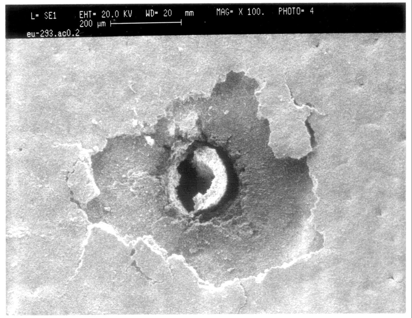
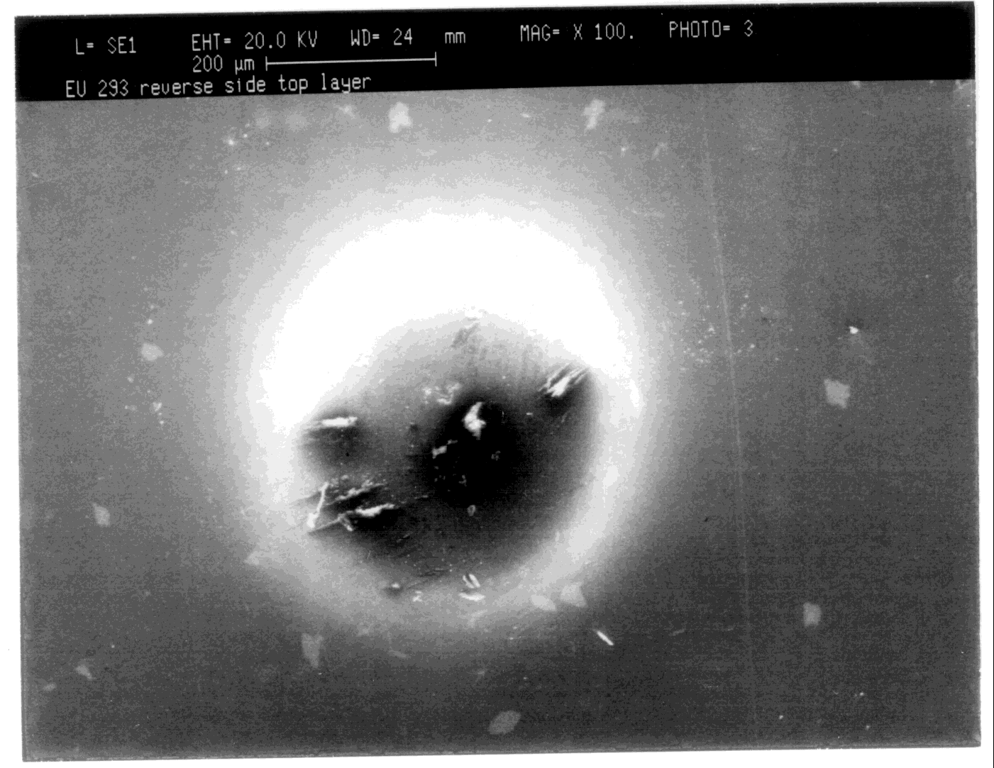
The impact did not penetrate the top layer of the plume impingement shield. The morphology of the impact on the top layer was quite distinct due to its painted surface. An area around the impact hole shows that the paint has been fractured and ejected (figure 16). The brittle nature of the paint is apparent. A hole in the paint is clearly visible, but examination of the rear side of the layer under the SEM shows that the hole does not penetrate the layer (figure 17). A video microscope image of the reverse side shows that there is a spalled circular area on the Kapton surface, but no through hole (figure 18). The second layer and separating Dacron net are untouched.
| Layer Thickness | Material Layer | Long Axis Hole D (mm) | Short Axis Hole D (mm) |
|---|---|---|---|
| 280 um | Paint-Al-Kapton 1 | 0.67 dam. 0.22 hole | 0.6 dam. 0.17 hole |
| 280 um | Paint-Al-Kapton 2 | No Damage | |
| 75 um | Al-Kapton 3 | ||
| 75 um | Al-Kapton 4 |
EDX analysis around the impact revealed only that the paint ejected had not gone through the paint layer and exposed the next layer of Aluminium. Nothing was detectable through the 'hole' in the paint. Despite many ejecta clustering around the hole, all of them showed a paint signature and must have been created by heating and ejection during the impact process (spectrum 9). No conclusions could be drawn regarding the origin of this impact particle.
Further Activities
ESCA analysis of the deposits on the second layer of EU-119.db2.1 will be performed. These may shed light on the chemical nature of the droplets found on the surface of the second layer of this impact.
Analysis of 66 other impacts on EURECA MLI by Open University, GB is in process. This set of results will provide a useful database of the chemistry of impacting particles on EURECA.
Also in process are a series of calibration experiments performed in laboratory facilities. At EMI Freiburg, particles of aluminium and glass of 0.5 to 1 mm diameter have been shot with a light gas gun onto EURECA type 6 MLI at 0¡ and 60¡ angle of incidence. In a different particle size range, glass spheres of 50 to 200 µm have been accelerated using a plasma accelerator onto the same MLI at the Technical University of Munich. The results of these experiments are being compiled by the University of Darmstadt and should be available soon. They will hopefully enable relationships between the size of the particle and the damage in the MLI to be developed.
Conclusions
The conclusions can be resumed in the following points:
- Morphology of impact damage depends heavily on the surface impacted and the size of the impacting particle. The following morphologies were observed:
- Betacloth melts and breaks giving an irregular hole. The Teflon layer around the hole is shattered and ejected, producing small pieces of Teflon and loose fibres.
- Paint shatters, not necessarily at the interface between paint and aluminium.
- 75 µm Aluminised Kapton chars and decomposes giving a circular hole.
- 7.5 µm Aluminised Kapton chars and tears leaving a ragged hole with cracks leading from it.
- Dacron net melts leaving blackened ends.
- The EU-293.ac0.2 impact remained in the first layer of the plume impingement shield (layer thickness 280 µm). The EU-143.g2.1 impact penetrated eleven layers of type 6 MLI (total thickness 352.5 µm). The EU-119.db2.1 impact penetrated the first layer of the type 6 MLI (layer thickness 210 µm).
- No deductions on the sizes of the impactors can be made until the results of recent calibration experiments have been analysed. However, it seems safe to say that the EU-143.g2.1 had more momentum than the other two impacts.
- Chemical characterisation was complicated by the vast array of different elements in the blanket materials. Pieces of shattered Teflon, broken glass fibres and strands of Dacron net were littered around the impact sites on the type 6 MLI. Organic salts and minute pieces of stainless steel were also found.
- It seems that the impact EU-119.db2.1 may have been caused by an aluminium impact particle. In order to confirm or deny this, it is planned to make a detailed analysis using ESCA surface analysis on the second layer of the blanket.
- The EU-143.g2.1 impact shows signs of being caused by a particle containing Si, Ca, Al, Mg, S, O. The residues seen were usually in the form of droplets. Unfortunately the glass fibre composition is also: Si, Al, Ca, Mg, O. In order to distinguish whether the droplets are simply melted bits of glass fibre or some sort of silicate micrometeoroid, further analysis is necessary. The residues are too small for a Transmission Electron Microscope examination of the crystal structure, but an ESCA surface analysis may provide conclusive information.
- It was found impossible to deduce anything from the analysis of EU-293.ac0.2. No residues were detected.
References
- Unispace Kent/SAS/C.R. Maag/Mare Crisium/CERT-ONERA (1994) "EURECA Micrometeoroid and debris post flight investigation-final report", Contract No. 10522/93/NL/JG.
- Kelley J. and Martino R. (1989) "EURECA flight thermal analysis report", EC-RP-AI-058, Issue 01.
Figures
(Figure Not Available)
Figure 1: The EURECA spacecraft and it's orientation
axes (figure not available).
(Figure Not Available)
Figure 2: The position of the different MLI
types on the EURECA spacecraft body (after Kelly & Martino, 1989) (figure
not available).
Figure 3: The construction of Type 6 MLI according
to project documentation (Kelly & Martino, 1989).
Figure 4: The construction of the plume impingement
shield (Kelly & Martino, 1989).
 (png
image size = 720Kb)
(png
image size = 720Kb)
Figure 5: Video microscope image of the top
betacloth layer of EU-119.db2.1.
(Figure Not Available)
Figure 6: SEM secondary electron image of the
top betacloth layer of EU-119.db2.1 (figure not available).
 (png
image size = 738Kb)
(png
image size = 738Kb)
Figure 7: Close up SEM secondary electron image
of the top betacloth layer of EU-119.db2.1.
 (png image size = 713Kb)
Figure 8: Video microscope image of the second
aluminised Kapton layer of EU-119.db2.1 showing cloud of deposits.
 (png image size = 748Kb)
Figure 9: SEM secondary electron image of the
second aluminised Kapton layer of EU-119.db2.1.
 (png image size = 727Kb)
Figure 10: Video microscope image of top betacloth
layer of EU-143.92.1.
 (png image size = 713Kb)
Figure 11: SEM backscattering image of the
top betacloth layer of EU-143.92.1.
 (png image size = 721Kb)
Figure 12: Video microscope image of the second
aluminised Kapton layer of EU-143.92.1 (diameter of hole is 1.3 mm).
(Figure Not Available)
Figure 13: SEM secondary electron image of
deformations in Kapton in fiery halo around hole in second layer of EU-143.92.1
(figure not available).
 (png image size = 3.2Mb)
Figure 14: SEM secondary electron images of
the holes in aluminised Kapton layers 3 to 13.
(Figure Not Available)
Figure 15: Particles found around hole on
layer 7 of EU-143.92.1 (figure not available).
 (png image size = 750Kb)
Figure 16: SEM secondary electron image of
top paint layer of EU-293.ac0.2 on plume impingement shield.
 (png image size = 760Kb)
Figure 17: SEM secondary electron image of
reverse side top layer of EU-293.ac0.2 showing non-penetration.
(Figure Not Available)
Figure 18: Video microscope image of reverse
side of top layer of EU-293.ac0.2 showing aparant spalling of Kapton (figure
not available).
Spectra (Images not available)
- Spectrum 1: EDX analysis with open window at 20 KeV of betacloth glass fibres on EU-119.db2.1.
- Spectrum 2: EDX analysis with open window 20 KeV of deposits on second layer of EU-119.db2.1
- Spectrum 3: EDX analysis with open window and 20 KeV of layer 2 of EU-143.92.1 far from impact (reference spectrum of aluminised Kapton)
- Spectrum 4: EDX analysis with open window at 20 KeV of EU-143.92.1 of particles around hole in second layer.
- Spectrum 5: EDX analysis with open window at 20 KeV of EU-143.92.1 of particles found around hole on layer 4.
- Spectrum 6: EDX analysis with open window at 20 KeV of EU-143.92.1 of particles around hole on layer 4.
- Spectrum 7: EDX analysis with open window at 20 KeV of EU-143.92.1 of particles around hole on layer 7.
- Spectrum 8: EDX analysis with open window at 20 KeV of EU-143.92.1 of particles on layer 11.
- Spectrum 9: EDX analysis with open window at 20 KeV of EU-293.ac0.2 analysis of area outside impact gives same spectrum as around and inside impact.