

EURECA MLI Reports
EURECA Multi-Layer
Insulation Impact Morphology and Residue Analysis
Final Report June 1995
Prime Contractor:
Dr I. P. Wright
Planetary Sciences Unit Cosmic Mineralogy
The Open University,
Walton Hall Dept. of Mineralogy,
England
with
Ms A. Sexton & Dr M. M. Grady
The Natural History Museum Milton Keynes MK7 6AA,
England. Cromwell Road,
London SW7 5BD, England.
I.P.Wright@open.ac.uk
M.Grady@nhm.ac.uk
European Space Agency/ESTEC
Contract No: RFQ/3-8001/94/NL/JG
Table of Contents
- 1. Introduction
- 2. Thermal Insulation Blankets
- 2.1 MLI
- 2.2 Others
- 3. Samples
- 4. Photographic examination
- 4.1 Equipment and Methods.
- 4.2 Results of the Optical Survey
- 4.2.1 Surface-sited particles
- 4.2.2 Impact Features
- 4.2.3 Size of penetration feature
- 4.2.4 Flux Calculations
- 5. Delamination of MLI and Curation of Samples
- 5.1 Procedure.
- 5.2 Impact Characteristics
- 5.3 Impact Directions
- 6. Chemical Analyses of Particles and Residues
- 6.1 Analysis of Beta-Cloth
- 6.2 Preliminary Analyses
- 6.3 Detailed Study of Sample 110.dg1.1 (Susan Lindsay)
- 6.4 Main Analysis Program
- 6.5 Analysis of Surface-Sited Particles
- 7. Conclusions
- 8. Acknowledgements
- 9. References
- Appendix A1: Index of images on Photo-CD
- Appendix A2: Impact features on EURECA MLI blankets
- Appendix A3: Cumulative impact flux on EURECA
- Appendix A4: Composition of particles and residues associated with impact features
1. Introduction
This report details the results of the Impact Morphology and Residues Analysis project carried out on multi-layer insulation blankets recovered from the exterior surfaces of the European Retrievable Carrier. For reasons of brevity, "Multi-Layer Insulation" is henceforth referred to as MLI, and "EUropean REtrievable CArrier" as EURECA. There were two major aspects to the work: the first involved a detailed photographic survey of the impact features recorded by the MLI blankets, while the second was an attempt to constrain the nature of the impacting materials by chemical analyses. Preliminary reports of the work undertaken herein are given in Grady et al. (1995a) and Grady et al. (1995b). Photographic prints of the impact features, plus their images on two photo-CDs (CD1 and CD2), were transferred to ESA in September 1994, at the completion of the first phase of the project (the optical survey). An index of the images on CD1 and CD2 is given in Appendix A1. The Space Shuttle Atlantis (STS-46), carrying EURECA was launched from Cape Canaveral on 31st July, 1992. The satellite was deployed using the remote manipulator system of the Shuttle on 2nd August, 1992, at an orbital altitude ca. 426 km, ascending to its operational orbit of ca. 500 km within 5 days of deployment. After orbiting the Earth for approximately 11 months, EURECA was retrieved by the Space Shuttle Endeavour (STS-57) on 24th June, 1993, and returned to the Kennedy Space Center. Figure 1 is a schematic diagram of EURECA, to indicate its main surface orientations: the sun-pointing orbital geometry of the satellite ensured that the +Z face of EURECA was the one which always faced towards the sun.
![]() (png
image size = 147Kb)
(png
image size = 147Kb)
Figure 1: The EURECA Spacecraft
Post-flight payload de-integration of Eureca took place at the Astrotech Facility, Titusville, Florida, during which time a micrometeoroid and debris investigation was carried out (Prime Contractor: UniSpace, Kent; ESA Contract No. 10335/93/NL/JG). An overview of the EURECA post-flight analysis program is given in Aceti et al. (1994). The MLI blankets which covered EURECA were primarily intended for thermal control of the spacecraft. However, from the nature of their construction (see Section 2) it was anticipated that they may have been effective at decelerating and subsequently capturing particles from low Earth orbit (i.e., natural micrometeoroids and space debris). A total of 37 of the 99 thermal blankets, plus two aluminium-painted scuff plates were scanned, and 86 impact sites idenpngied. Eleven of the impacts were in the scuff plates, two in the ESA/ERNO sign and the remaining 73 in the thermal blankets. The main aim of this project was to attempt to characterise the nature of the particulate materials that had impacted the EURECA spacecraft - in particular it was hoped to provide an assessment of the relative proportions of natural samples and space debris. The work has some parallels with the post-flight investigations of LDEF (the Long Duration Exposure Facility, e.g. Zolensky et al., 1993) and the results can be considered complementary. Note that as part of the scienpngic payload of EURECA, there was an experiment dedicated to particle collection (TICCE, the TIme-band Capture Cell Experiment), preliminary results from which can be found in Brownlee et al. (1994) and McDonnell (1994).
2. Thermal Insulation Blankets
The two main thermal insulation blankets used on EURECA were Type 3 and Type 6 MLI. In addition, several other blanket constructions were used in specific applications. These include a hybrid MLI, the plume impingement shield, a double Kapton shield, and single-sheet painted materials. The following are brief descriptions of these materials, based on information from Document No. EC-RP-AI-058 produced by Aeritalia Space Systems Group (1989).
2.1 MLI
Type 6 MLI covered much of the exterior surfaces of EURECA, and was the most common blanket type encountered in this project (Figure 2). It consists of a top (outer) layer of woven Teflon-coated fibreglass (beta-cloth), below which was a light-block layer consisting of perforated 75 mm-thick Kapton, coated on the inner side with a vacuum-deposited layer of aluminium, covered by an acrylic overcoat ("single-aluminised Kapton", SAK). Below this are 19 reflective layers, each consisting of ( 7.5 mm-thick perforated Kapton coated on both sides with aluminium and an acrylic overcoat ("double-aluminised Kapton", DAK). The reflective layers are separated by 20 layers of Dacron net. The layers are perforated to allow outgassing products to escape. The final, innermost layer (the internal layer) is of 50 mm-thick Kapton coated with aluminium, the inner surface of which is painted black (Electrodag 501).
![]() (png
image size = 118 Kb)
(png
image size = 118 Kb)
Figure 2: Schematic representation of Type 6 MLI blanket
The Type 3 MLI was simply composed of beta-cloth, a Dacron separator and an internal layer. The materials and dimensions are the same as those given above for Type 6 MLI. One blanket (sample 239.g3.1) appeared to be a hybrid form of MLI comprised of 5 separate layers: three layers of beta-cloth and two internal layers, arranged in an alternating fashion so that beta-cloth was present on both the top and bottom surfaces.
2.2 Others
One impact hole (239.ac0.2) was recorded in the blanket removed from around the radiators on EURECA. Berthoud (1995) refers to this material as a plume impingement shield, positioned around the radiator to protect the equipment from ejecta from the thrusters. This sample was one of three returned to ESA for investigation, and is described by Berthoud (1995) as 5 layers of SAK, the top (or space-facing) two layers of which were coated with white paint (PSG-120-FD) on the aluminium side.
Two blankets were comprised of a double Kapton shield (samples 292.e3.1 and 294.j5.1); two further samples were of single sheets of unknown composition, but possibly Kapton. One of these blankets was painted green (102.e4.1) and the other red (134.d2.1).
3. Samples
Following the preliminary examination undertaken by UniSpace Kent et al. (1994), 68 of the blankets were cut into pieces (approximately 10 x 10 cm squares), each square believed to incorporate one impact feature (contract to Mare Crisium). To prevent individual samples from separating, each section of blanket was stapled around the edges, then sealed in a bag; groups of approximately ten blankets were further sealed inside a thick plastic envelope. These were delivered to the Natural History Museum, London, where the work detailed herein was undertaken. In addition to samples containing impacts, two large-area pieces of Type 6 MLI were supplied for exploratory handling purposes.
Of the 68 samples, three were selected at random by ESA and donated to ESTEC to enable a contemporaneous study using the Centre's own analytical facilities (the results of which can be found in Berthoud, 1995). The three samples were 119.db2.1, 143.g2.1 and 293.ac02.2 (representing two samples of Type 6 MLI and the only example of an impact into the plume impingement shield). Note that for completeness, these impacts were included in the optical survey, carried out before the samples were transported to ESTEC (see Appendix A1).
In summary, this report describes impacts into 65 areas of thermal insulation blanket (Appendix A2). Of these, 35 were in Type 6 MLI (M6), 13 in Type 3 MLI (M3), 1 was in the hybrid MLI (MH), 2 were in the double-Kapton shield (KK) and 2 in single-sheet foils (SS). The construction of the remaining 12 is not known: no impact features were observed on the surface, thus the blankets were not delaminated. However, in each case, the topmost layer was beta-cloth, implying that these 12 samples were either Type 3 or Type 6 MLI (M3/6).
4. Photographic examination
4.1 Equipment and Methods.
The preliminary requirement of the project was to make a detailed optical survey of all potential impact sites. Optical examination of each blanket was undertaken using a Leica Wild M8 binocular microscope. The diameter of each impact was measured using an eyepiece graticule, which had been calibrated against a graduated standard 1 cm scale-bar. Two measurements were made for each impact, using the highest magnification setting (x75), at right angles to each other, and a mean diameter calculated, assuming an ellipsoidal shape for the holes (Appendix A2).
Each impact was then photographed at x9, x18, x37.5 and x75 magnifications, achieved by a combination of the standard x6 to x50 click-stop/zoom facility plus an additional x1.5 light accessory module. The blankets were illuminated from a low-angle using blue- and diffuse-filtered light through twin swan-necked light guides, which gave shadow-free images. The light source was a Volpi Intralux 4000 fibre-optic cold-light illuminator, fitted with a tungsten bulb. Pictures were taken on 35 mm film (Kodacolor 200), using a Wild MPS 52 camera with integrated light focus and Leitz Photomat controller.
The photographic prints are in the two volumes supplied to ESA in September 1994. The images are also contained on Photo-CDs CD1 and CD2. An index of the images on each Photo-CD is given in Appendix A1. The photographic negatives accompany this document.
4.2 Results of the Optical Survey
4.2.1 Surface-sited particles
During preliminary investigations, the surfaces of individual MLI blankets were subjected to wide-area optical investigation, which revealed that many different types of small particles were frequently present, some of which were close to penetration features, but many of which were simply dispersed across the beta-cloth. The rather widespread occurrence of the particles suggests that contamination could be a problem. This is perhaps not surprising since, within the framework of the EURECA program, it was presumably not originally conceived that there would be such detailed post-flight investigations.
The magnitude of the contamination problem is illustrated by the fact that of the 65 blankets received, 11 of the features initially idenpngied as impacts were actually the result of particulate matter present on the surface of the blanket (Type 3 or 6 MLI in every case), and not a penetration event. The impact features listed in Appendix A2 which do not have measurements of crater size represent the surface-sited particles; in addition a separate list is given in Table 1, along with further details. All the particles were photographed, and their images are included in the photograph album and photo-CD (CD3) which accompany this report.
| Sample | Photo-CD & Image No. | Details |
| 106.1 | (3) 15 | Several |
| 106.1b | (2) 16 | No particle or hole, but a "burn" on the beta-cloth |
| 119 Core A | (3) 13,14 | Several |
| 119 Core B | (3) 1,2 | At least 6 (Fig. 3b) |
| 125 Core B | (3) 5 | 1 fragment of beta-cloth fused into the surface (Fig. 4a), plus several other particles, one of which was mainly Zn |
| 125 Core D | (3) 3,4 | 1 glassy particle, mainly Zn and Cl (Fig. 4b), plus 1 fragment of beta-cloth residue |
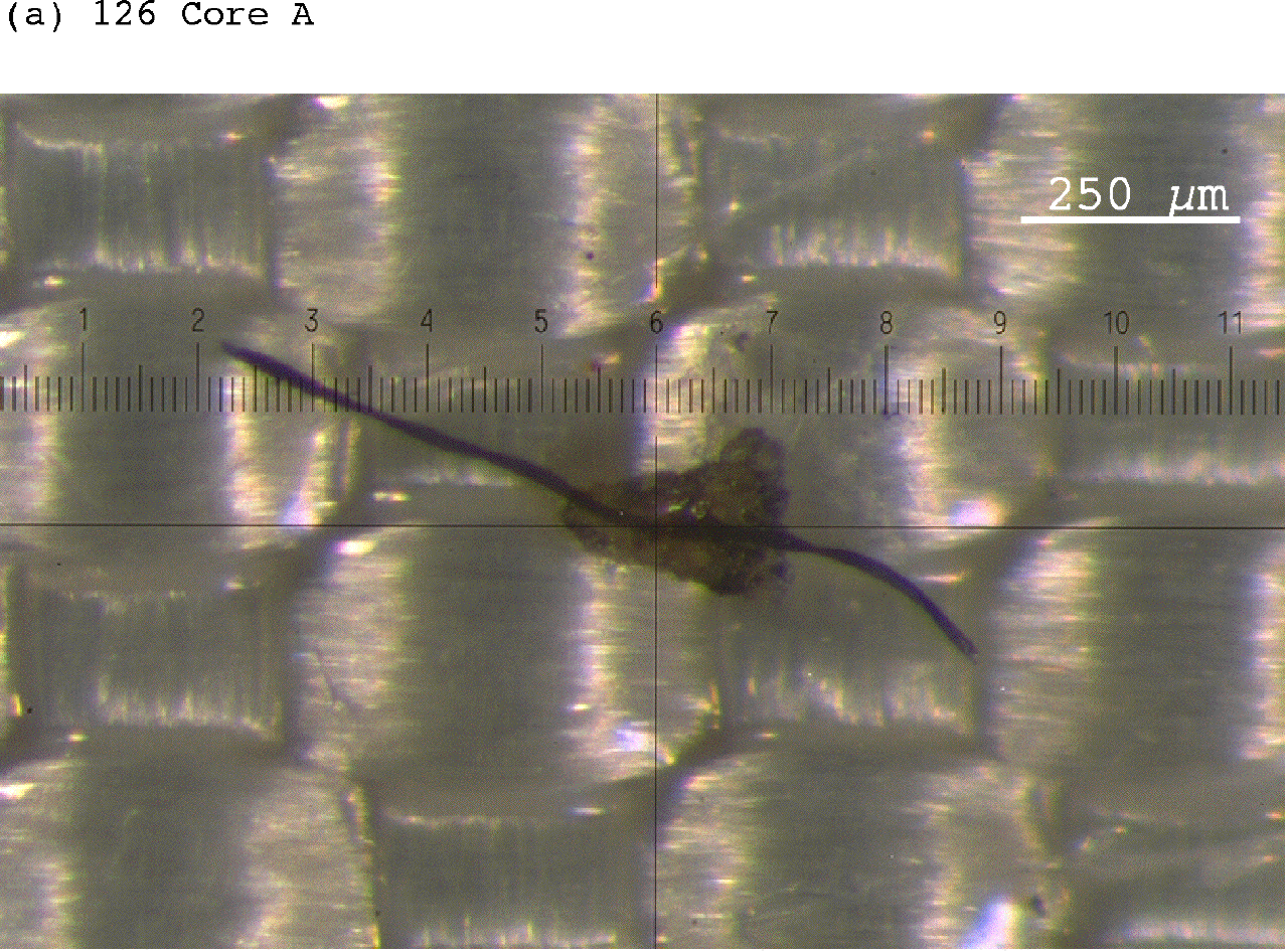
| 126 Core A | (3) 6,7 | At least 4 (Fig. 3a) |
| 130.ad4.1 | (3) 10 | 1 particle |
| 131.bb2.1 | (3) 8 | 1 particle |
| 240.bf4.1 | (3) 11 | Several |
| 252.1 | (3) 12 | 2 particles (Fig. 4c) |
| 295.b4.1 | (3) 9 | 1 particle |
Table 1: Surface-sited particles.
Physically, the surface-sited particles demonstrate a wide variety of different characteristics. For instance, one is associated with a fibre (126 Core A, Fig. 3a). Others are rather angular and appear, optically at least, to be fragments of paint (e.g., 119 Core B, Fig 3b), perhaps introduced during deintegration when the blankets were stacked on top of each other. However, three of the surface-sited particles are slightly fused into the top-most beta-cloth (125 Core B, Figure 4a; 125 Core D, Figure 4b and 252.1, Figure 4c). These particles might not be contaminants, but could represent impacts of extremely low-velocity, hence they were subjected to chemical analysis (see Section 6.5). However, apart from the fused particles (which subsequently appeared to be space debris), it was appreciated that the surface-sited particles were most probably contaminants introduced before the original preliminary survey (which had mistakenly idenpngied them as impact sites).
4.2.2 Impact Features
The remaining 54 impact features can be sub-divided into 51 single events and 3 multiple events. The three samples containing multiple impacts are 121.bh1.1 (2 impacts), 227 Core A (3 impacts) and sample 227 Core B (4 impacts). The features were photographed individually, and have been given a modified sample number. There were therefore 60 recorded impact events. However, one of the impact events included in the optical survey (106.1b) appears to be a circular depression in the beta-cloth, but with no discernible particles on the surface (Table 1). Thus, there is a total of 59 penetrating impact events. Of these 59 events, 38 are in Type 6 MLI, 16 in Type 3 MLI, 1 is in hybrid MLI, 2 in double-Kapton, and 2 in single-sheet foils (Appendix A2). Although all the images are in the documentation previously supplied to ESA, a typical example of the impact feature in a blanket is shown in Figure 5.
 (png
image size = 5.5Mb)
(png
image size = 5.5Mb)
Figure 3a: Surface-sited particles - 126 Core A.
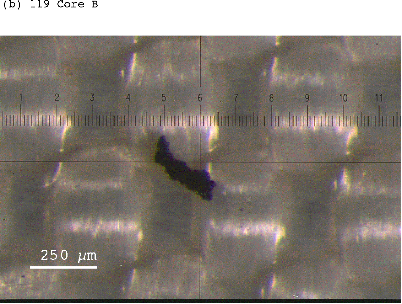
Figure 3b: Surface-sited particles - 119 Core B.
Figure 4a: 125 Core B.
Figure 4b: 125 Core D.
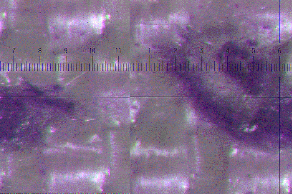
Figure 4c: 252.1.
![]()
Figure 5
In most cases, it is known which specific face of the satellite a particular blanket was sited, hence it is possible to look at the distribution of impacts across EURECA (Figure 6). Where the position of an impact feature was given as a combination of faces (Appendix A2), the number of impacts was divided evenly between the faces in question. Several impact features were on blankets from unassigned locations, and are therefore not included in Figure 6. It is apparent that the distribution is not equal across the X and Y faces, even though the satellite constantly rotated. The +Z face pointed sunwards (Figure 1), thus the -Z face was always in shadow, and has the lowest number of impact features. It is impossible to evaluate the significance of these figures, given that less than 50% of all the blankets covering EURECA were examined in the post-flight investigation (UniSpace Kent et al., 1994).
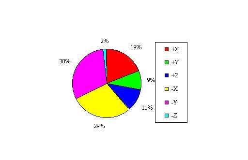
Figure 6: Distribution of impact features by face
4.2.3. Size of penetration feature
Figure 7 is a histogram of the frequency distribution of impact diameters from 62 penetration features on the outermost layer of the EURECA thermal blankets (59 NHM/OU specimens, plus 3 ESA specimens). The distribution is approximately bimodal, with maxima at 250 - 350 mm (n = 20; 32%) and 400 - 500 mm (n = 11; ~ 18%). The small number of events precludes rigorous conclusions to be drawn, but it is possible that the hole diameter might be related to impact velocity, and thus to composition, if natural micrometeoroids and space debris had differing velocities.
![]()
Figure 7: Frequency distribution of impact hole size for all EURECA samples
Figure 8 shows the data from Figure 7, sorted by blanket type. There is no relationship between hole diameter and the thickness of the underlying blanket.
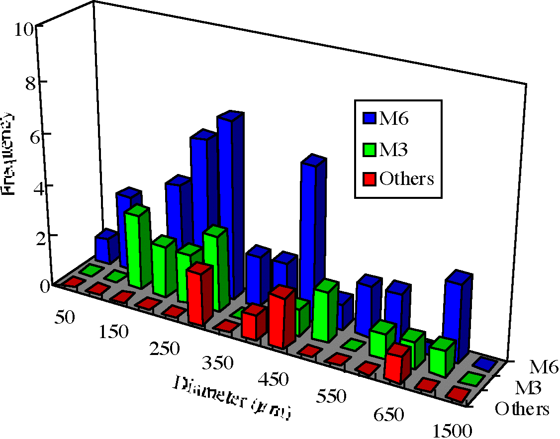
Figure 8: Distribution of hole size with blanket type
4.2.4. Flux Calculations
Given that the time which EURECA spent in orbit and the areas of blanket scanned are known, it is possible to make an estimate of the flux of impacting material to the Earth at the operational altitude of ~ 500 km. Following the model of UniSpace, Kent et al. (1994), a total cumulative impact flux distribution for EURECA was calculated (Figure 9). The data used are given in Appendix A3. The cumulative flux distributions for each face of EURECA are also given in Figure 9, along with data for LDEF, for comparison (McDonnell and Stevenson, 1991). Note that the LDEF data are normalised for an aluminium impact surface, whilst the EURECA data are not. As Figure 9 shows, the cumulative flux distribution for EURECA is very similar to that for LDEF, implying that the total flux of material (debris plus natural micrometeoroids) has not changed significantly between 1984 - 90 (when LDEF was in orbit) and 1992-93 (when EURECA flew), or at the different orbital altitudes (475 - 330 km for LDEF, vs. 500 km).
![]()
Figure 9: Cumulative Impact Flux Distribution
5. Delamination of MLI and Curation of Samples
Following the optical survey of the outer surface of the MLI blankets, a search was made for potential impactors, or residues thereof. At the outset, it was anticipated that scientists from the research community might have an interest in acquiring samples from the MLI blankets for further study. Therefore, during this search, each layer of the blanket was removed and stored in a separate receptacle. In this way, it is possible to retrieve a specific layer from any impact feature for research purposes. The EURECA samples are currently held in a clean room at the Natural History Museum in London.
5.1. Procedure.
Prior to delamination of the MLI blankets, each sample was cut to dimensions of ( 2 x 2 cm, using a razor-edged stainless steel guillotine. To prevent the samples from separating, they were stapled together at one edge. In this way, successive layers of the MLI blankets could be viewed optically and then removed leaving the rest of the MLI stack intact. As each layer was removed it was viewed on its top and rear surfaces to determine whether or not particulate or residual matter was present, then stored in an individual specimen box. In addition, the pieces of Dacron netting that separate the reflective layers in each specimen were collected and stored together, although it is not anticipated that these materials are likely to be of scienpngic interest.
As each MLI blanket was separated into its constituent layers, attempts were made to determine the sizes and the relative offsets of the holes in successive layers (the latter in an effort to derive impact directions, see section 5.3). However, the aluminium foils of the reflective layers within Type 6 MLI were often quite severely torn by the impact, precluding accurate measurements. The measurements made are not included in this report, but are available from the authors on request. The characteristics of each surface were noted - specifically, whether or not particles or residues were present. These observations were noted and are reproduced in Appendix B, which shows for each impact feature a schematic cross-section through the MLI. Also recorded are the layers at which the individual impacting particles stopped. Note that in most cases the particles were stopped within the MLI; however, in 4 samples of Type 3 MLI (147.ah2.1, 239.f2.1, 251.1 and 811.db8.1) the impactor traversed the whole of the blanket and exited from the rear side. Also, the two samples of single sheet material (102.e4.1 and 134.d2.1) were completely punctured, leaving no visible trace of the impactors. These samples are marked with an asterisk in Appendix A2. For those samples not completely traversed by the impactor, the undamaged layers were left stapled together and curated in a separate specimen box.
For the first few impact features studied, optical photographs were taken of each layer during delamination of the MLI foils. Little information is gathered from the photographs, especially in the case of the reflective layers from the Type 6 MLI, due to problems with the light used for illumination scattering off the surfaces of the torn and twisted foils. Notwithstanding this, the images are included in the photograph album and photo-CD (CD3) which accompany this report. Secondary electron scanning electron microscope (SEM) images were taken of several foils. They also add little information, but four images are shown in Figure 10, to give an example of the type of images recorded. Clearly, whole field-of-view pictures only attest to the way in which the reflective layers become damaged by the impacting particles. As such it was decided not to acquire SEM images during the subsequent phase of the investigation.
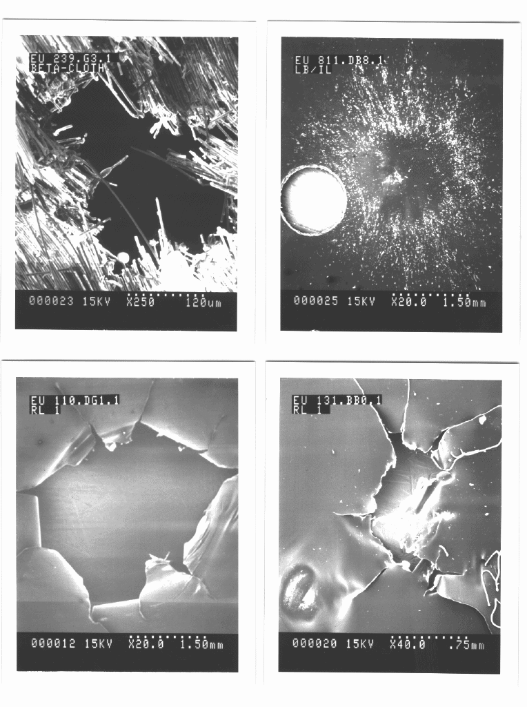
Figure 10: Secondary electron SEM images of layers from EURECA MLI blankets.
5.2. Impact Characteristics
As detailed above, four of the Type 3 MLI blankets and the two single sheet foils were completely penetrated during impact. For all other samples the impactor must have come to rest within the blankets. Figure 11 shows the frequency of the number of layers penetrated within the Type 6 MLI (the results are from the 38 samples analysed herein plus the two surveyed by Berthoud, 1995). Although there are insufficient data to distinguish unambiguously any trends, it is apparent that ( 75% of the particles are stopped within the first 6 layers; ~ 50% were stopped after traversing one layer (i.e. beta-cloth only, any particles coming to rest on the underlying light block layer). In comparison, 12 out of 16 particles (75%) were stopped by the beta-cloth layer in Type 3 MLI. One tentative conclusion is that the distribution of impact depths could reflect the incidence of particles of differing velocities or masses.
Figure 11: Number of layers penetrated in Type 6 MLI
There are common features in all the samples of Type 6 MLI which were penetrated through several layers. Firstly, in going through the beta-cloth, then the light-block layer, to the first reflective layer, the impact hole always becomes progressively larger. This is presumably a reflection of the differing strengths (and thicknesses) of the first three layers. Secondly, within the reflective layers stack, the maximum-sized impact hole generally occurs within an intermediate layer (i.e. not necessarily the first layer). This might be the result of the particle melting, and subsequently expanding or fracturing, as it travels through the MLI blanket. In a few cases (e.g., 132.ab5.1, 132.ba1.1 and 268.1) evidence of fracturing is given by the production of multiple holes within individual layers. Generally, though, the size of impact hole decreases through the last few impacted layers. These observations are recorded on the MLI cross-sections contained in Appendix B.
In Type 6 MLI, there is a significant positive correlation (r = 0.789; n = 40) between the size of the impact hole into the top, beta-cloth, surface, and the number of layers subsequently penetrated (Figure 12). This observation is consistent with the largest holes being made by the particles with the highest energy (which may be due to either high mass or velocity). The relationship becomes less significant, however, when the two largest features are removed from consideration.
Figure 12: Relationship between number of layers penetrated with hole size in Type 6 MLI
5.3. Impact Directions
In the initial stages of the delamination process, it was anticipated that it might be possible to obtain the impact direction of individual features through an appraisal of the relative offset of the holes in successive layers. The offset was measured (using the microscope graticule) from two fixed reference points in each layer, corresponding to two of the corners of the stapled MLI stack.
Initial worries about successive layers of foil slipping were unfounded. However, it readily became apparent that it was not possible to reconstruct impact directions, since many of the foil layers were torn by the projectile. Thus, although it was a straightforward matter to measure distances from a fixed reference point accurately, it was impossible, using an optical microscope at least, to assess where to assign the centres of the individual holes. This problem might be overcome using digital image processing techniques to derive the centre of each hole, and using this to compare to the reference point. The measurements taken are not included with this report, but are available on request.
6. Chemical Analyses of Particles and Residues
Particle chemistry was determined using an Hitachi 2500 SEM, fitted with a Link Analytical Systems AN 10000 energy-dispersive X-ray analyser (EDAX). Typical operating conditions were an accelerating voltage of 15 keV, and beam diameter ( 1 mm.
6.1. Analysis of Beta-Cloth
Before a satisfactory survey of any residues or particles could be undertaken, it was necessary to provide a baseline constraint on potential background signals from the beta-cloth. To this end, a full quantitative analysis of the beta-cloth was made, achieved by using a combination of Inductively Coupled Plasma Emission Spectroscopy (ICPES) and ignition analysis (for light elements such as H, C, and N). The results obtained are given in Table 2.
Table 2: Analysis of Beta-Cloth by ICPES.
| Species | Conc. (%) | Species | Conc. (ppm) |
| SiO2 | 39.2 | ZrO2 | 159 |
| TiO2 | 0.33 | Cr2O3 | 98 |
| Al2O3 | 11.0 | NiO | n.d. |
| FeO | 0.22 | BaO | 46 |
| MgO | 3.59 | SrO | 1282 |
| CaO | 13.3 | S | n.d. |
| Na2O | 0.49 | Cr | 67 |
| K2O | 0.09 | Ni | n.d. |
| H | 0.49 | Zr | 118 |
| N | 0.15 | Sr | 1084 |
| P2O5 | n.d. | Ba | 41 |
| C | 7.10 | ||
| F | 26.0 | ||
| Total | 101.96 | Total | 2895 |
A semi-quantitative analysis of the beta-cloth was also made by EDAX-SEM, by mounting a piece of beta-cloth end-on in epoxy, so that the interior of the fibres was exposed. This mounting geometry prevented interference from the outer coating of Teflon on the beta-cloth fibres. The recorded EDAX spectrum is shown in Figure 13.
Figure 13: Beta-Cloth spectrum from EDAX-SEM (ESA b3)
Since the glass fibres of the beta-cloth are comprised predominantly of the elements Si, O, Ca, Al and Mg, this is clearly not a good substrate upon which to search for natural micrometeoroid samples. Indeed, the only clear signals are likely to come from obvious contaminants or space debris particles; the problem here is that it may be somewhat difficult to choose between these options. It thus seemed more appropriate to concentrate the search for representative fragments or residues of the impactors within the relatively deeper layers of the MLI. An advantage with this approach is that because the inner layers are conducting they do not need to be coated to avoid charging. Additionally it may be expected that levels of contamination may be somewhat lower than on the surface of the beta-cloth. However, there is an immediate problem; it is clear from the visual observations of the beta-cloth that the individual fibres may have in some cases shattered and become displaced inwards towards deeper levels of the MLI. Additionally, beta-cloth fibres that were heated and melted by the impacts may have recondensed within the MLI. Thus, it should be anticipated that within a MLI stack there could be many unmelted fragments or condensed residues of beta-cloth. As an illustration of the potential magnitude of the problem it can be calculated that the quantity of beta-cloth removed during the formation of a 500 mm-sized impact hole amounts to about 0.5 m of glass fibre. If this were to shatter into pieces of 10 mm dimensions it would amount to 50,000 fragments. The formation of less than 1% of this quantity will clearly make the search for signs of the original impactor very difficult.
6.2. Preliminary Analyses
During preliminary analyses of particles associated with impact features it became rapidly obvious that there were often many particles associated with each event. Furthermore, an individual impact site may have many different types of particles or residues associated with it. For instance, in the case of 105.c1.1, several particles were analysed from the top surface of the beta-cloth; however, these were all found to be fragments of the beta-cloth itself. The sample 110.dg1.1 (ÒSusan LindsayÓ) is discussed in detail in section 6.3. For 210.ac2.1 a number of different types of materials were idenpngied, including those of an apparently pure calcium composition, many iron particles, salts (rich in K, Zn, Cl and S) and, inevitably, beta-cloth fragments. Similar particle types were encountered in the main survey (see Section 6.4 below). It would seem that the impactor that produced 210.ac2.1 was probably an iron particle; the salt component is a ubiquitous space contaminant, idenpngied previously on LDEF (Zolensky et al., 1993), and it is possible that the calcium represents an extremely fractionated beta-cloth composition (i.e. a condensed residue).
A conclusion of the preliminary survey was that it would be practically impossible to analyse all particles associated with each impact. Thus, it was decided during the main survey to make only one or two analyses at each impact feature, measuring the largest fragments or residues; clearly these may not have been representative. In order to try and gain an insight into the possible extent of this effect, one impact, 110.dg1.1, was selected for an extensive study. In this case 15 analyses of particles were carried out. The results are discussed in the next section.
6.3. Detailed Study of Sample 110.dg1.1 (Susan Lindsay)
The impact designated 110.dg1.1 (known as "Susan Lindsay") was found to have penetrated through a total of 15 layers of Type 6 MLI. Optical analysis had already shown that there were many particles associated with this event, on both sides of each layer. During preliminary analyses the chemical compositions of five separate particles were determined, to gain an impression of the likely nature of the particles. Note that all of these samples were located on the top surface of the beta-cloth. In addition to a fragment of beta-cloth, there were gold-rich and tin-rich particles. A further particle appeared to be a composite, containing an enrichment of certain rare-earth elements (REE) and a salt containing Na, K, Cl and S. Within the composite particle an area was discovered that appeared to be pure zinc.
As 110.dg1.1 was delaminated, four particles were removed from the Dacron separator, between reflective layers 4 and 5. Two of these appeared to be the result of condensed beta-cloth, one a salt particle and another a silicon-rich material (also containing some potassium). At this point in the investigation it was considered likely that 110.dg1.1 was produced by the impact of space debris. However, when the investigation proceeded down to reflective layer number 14 (i.e., the layer beyond which no obvious impact hole could be discerned) two particles of magnesium silicate were discovered. These are from single mineral grains and are considered most likely to have a natural origin. Note that on the same layer a beta-cloth fragment was idenpngied, as well as an iron particle. Iron without nickel is generally taken to be an indication of space debris, rather than a natural sample. Continuing the search below layer 14 showed more particles (beta-cloth fragments) associated with layer 16. It is unclear how particles could have reached this layer - perhaps there are small impact holes that are difficult to see. Alternatively the particles may have been transported through the (de-gassing) perforations of the MLI.
It is extremely difficult to assign an origin to the impactor that created 110.dg1.1. Ignoring the fragments and residues of beta-cloth (which are presumably a common product of all impacts into Type 3 or Type 6 MLI), there are metal-rich particles (REE, Zn, Sn, Au, Fe), salt particles (Na, K, Zn, Cl, S), a Si-rich particle, and what appears to be two fragments of a natural micrometeoroid. In other words there would seem to be a mixture of space debris and natural materials within one impact. It is likely that there was only one impactor, in which case, the Si-rich, iron and magnesium silicate particles are all from the same sample, perhaps an impactor of chondritic composition. The transient heating experienced during impact may have been sufficient to cause a serious fractionation of the constituent elements, resulting in the condensed residues observed. Note that all of these materials are found deep within the MLI stack, which is compatible with a high-velocity impact. The salt crystal present on the Dacron netting is a common space contaminant - materials of this nature are probably present on all exposed surfaces of MLI blankets (and, by extension, within impact holes). It is considered unlikely that the salt particle was responsible for forming the impact hole. The other materials associated with 110.dg1.1 (REE, Zn, Sn and Au) are all present on the surface of the beta-cloth and may simply represent condensates from impacts on other parts of the spacecraft.
Although the above explanation may appear self-consistent it is clearly open to doubt. An alternative is that there were two impacts within one hole (which seems immensely unlikely). What is concluded from the study of 110.dg1.1 is that it can be extremely difficult to constrain the nature of an impacting particle into MLI. Furthermore, the analysis of just one or two particles from an individual hole is likely to be somewhat misleading. Unfortunately, within the time constraints of the present study, this was all that was generally possible. To tackle the problem it is suggested that a future investigation should utilise an automated element mapping procedure, in order to idenpngy materials of interest.
6.4. Main Analysis Program
Notwithstanding the caveats of Section 6.3 (above), analyses of particles and residues from 38 of the 59 impact features have been carried out. For the remaining 21 samples, although there might have been large numbers of particles present, their dimensions were not sufficiently large to enable useful chemical analysis using SEM.
The analytical results obtained herein are given in Appendix A4. Note that in total, 75 individual analyses were performed. The spectra have been recorded digitally and are contained on the CD-ROM which accompanies this report. In order to rationalise the data, a tentative "particle description" has been assigned to each analysis (Table 3). Figures 14 - 18 show representative spectra of the different sorts of particle analysed.
Figure 14: (a) Organic salt particle (ESA 2d); (b) Sodium cloride (ESA 28a).
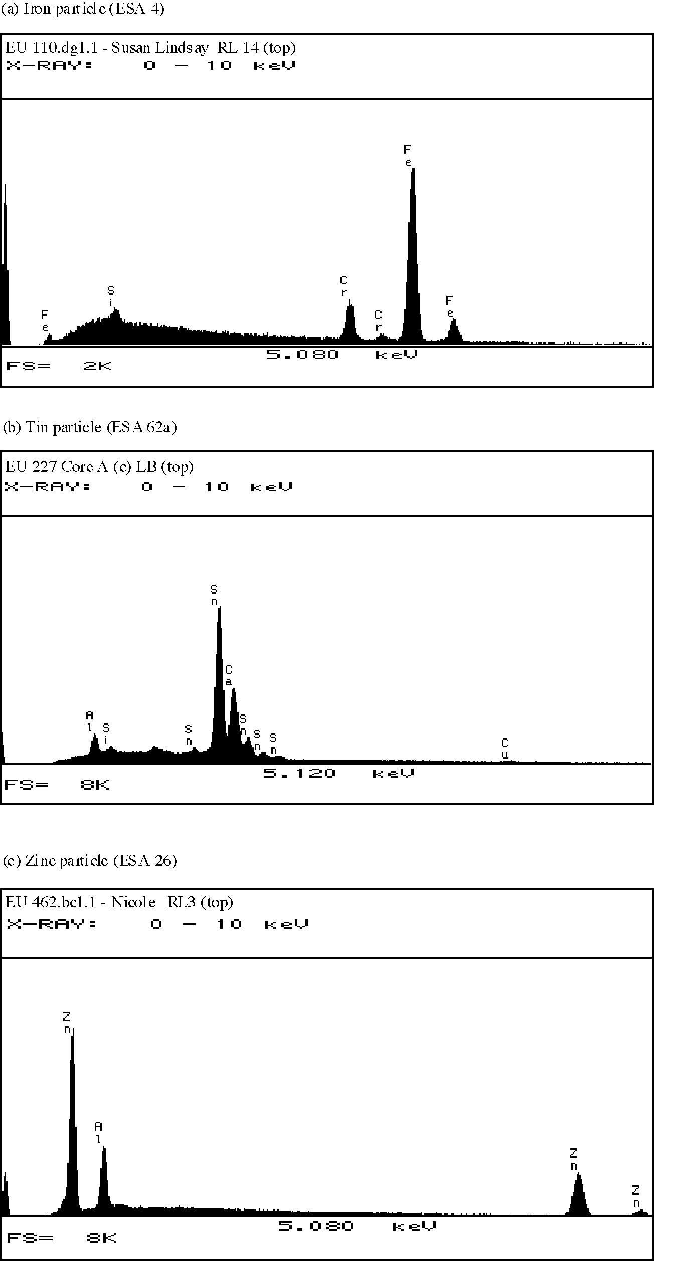
Figure 15: (a) Iron particle (ESA 4); (b) Tin particle (ESA 62a); (c) Zinc particle (ESA 26).
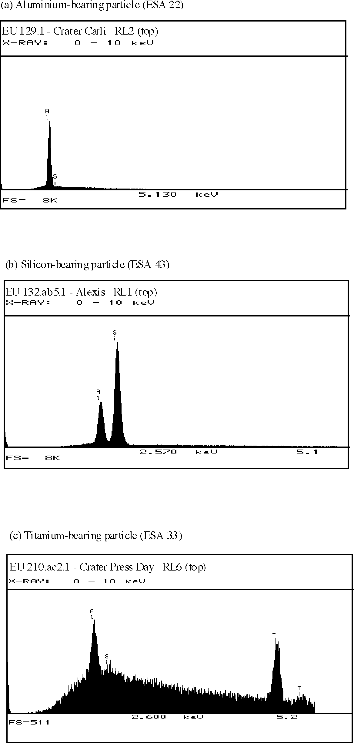
Figure 16: (a) Aluminium-bearing particle (ESA 22); (b) Silicon-bearing particle (ESA 43); (c) Titanium-bearing particle (ESA 33).
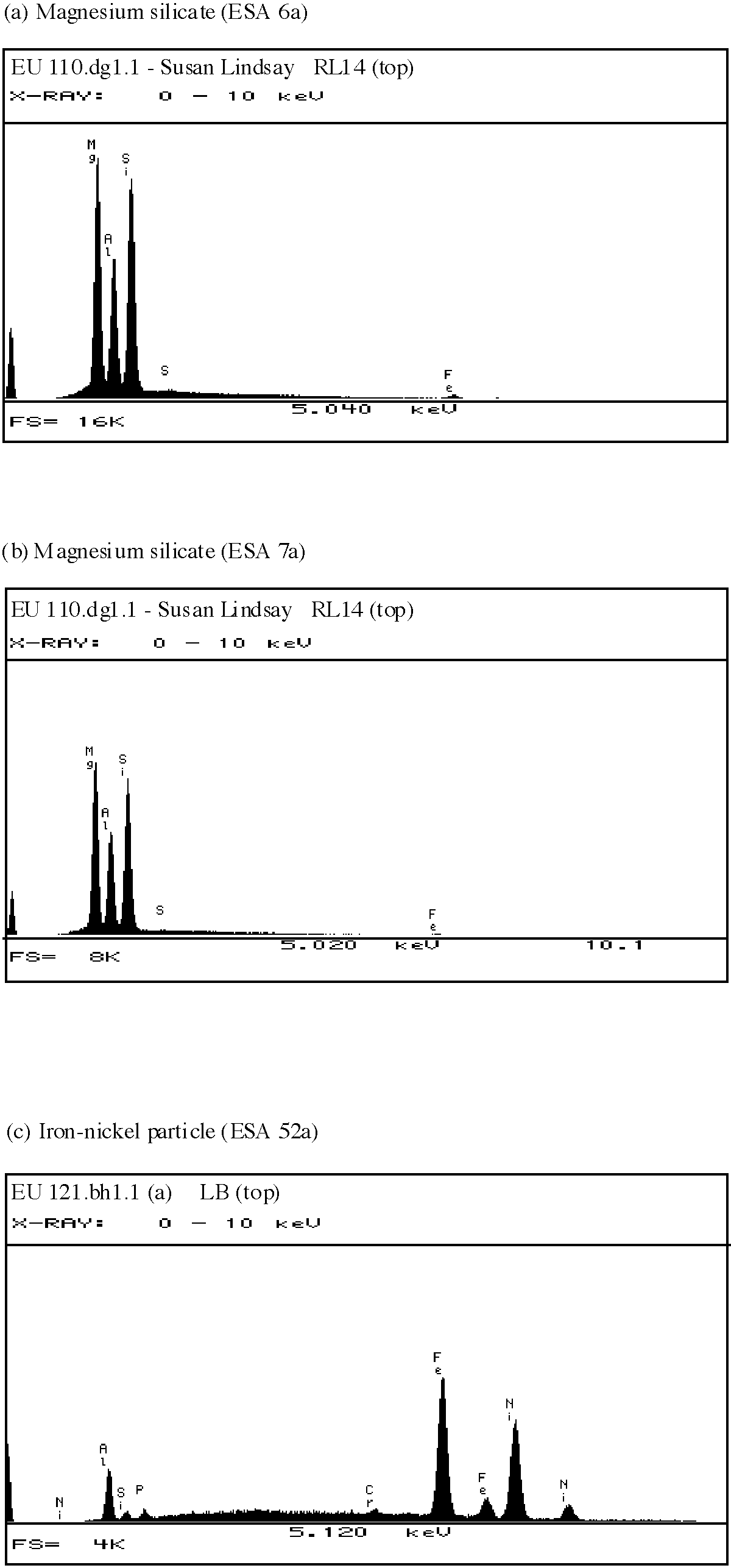
Figure 17: (a) Magnesium silicate (ESA 6a); (b) Magnesium silicate (ESA 7a); (c) Iron-nickel particle (ESA 52a).
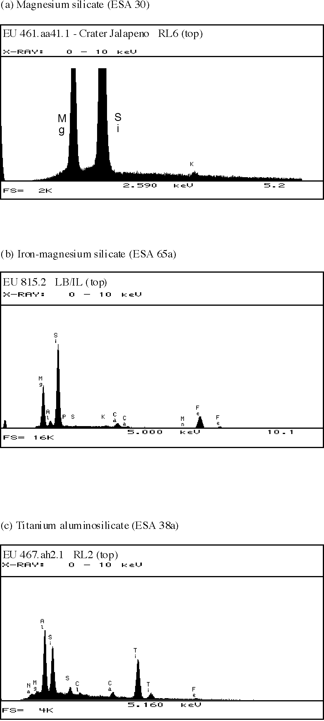
Figure 18: (a) Magnesium silicate (ESA 30); (b) Iron-magnesium silicate (ESA 65a); (c) Titanium aluminosilicate (ESA 38a).
Table 3: Summary of chemical analyses (75 analyses of particles or residues from 38 impact holes).
| Particle Description | Number | Particle Description | Number |
| Beta-cloth fragment | 25 | Ti, or Ti oxide | 2 |
| Beta-cloth fragment + salt | 2 | ||
| Beta-cloth fragment + Cu-Ni | 1 | Na, K, Zn, Cl, S salt | 4 |
| Beta-cloth residue (Ca-rich) | 6 | NaCl salt | 1 |
| Beta-cloth residue (Ca-poor) | 2 | Fe | 3 |
| Al, or Al oxide | 10 | Zn | 1 |
| Al, or Al oxide + salt | 1 | Sn | 1 |
| Si, Si oxide, or silicone | 5 | Magnesium silicate | 3 |
| Si, Si oxide, or silicone + salt | 1 | Iron-magnesium silicate | 1 |
| Si, Si oxide, or silicone + Fe-Ni | 1 | Titanium-aluminosilicate | 1 |
| Si, Si oxide, or silicone + Zn-Ni-Cu | 3 | Iron-nickel | 1 |
| Total | 57 | Total | 18 |
In order to provide a more useful grouping of the chemical compositional data, the results have been synthesised into Table 4 and Figure 19. These are extended to give Table 5 and Figure 20, which attempt to account for the analysis of composite materials (hence in this table the total number of analyses is ( 84). Finally, in Table 6 and Figure 21 the data for samples other than beta-cloth are presented, since it is certain that, although the beta cloth fragments are the result of impacts, they are not the cause.
Table 4
| Description | Number | % of Total |
| Beta-cloth | 36 | 48.0 |
| Al-bearing | 11 | 14.7 |
| Si-bearing | 10 | 13.3 |
| Ti-bearing | 2 | 2.7 |
| Salt | 5 | 6.7 |
| Metallic | 5 | 6.7 |
| Natural | 6 | 8.0 |
| TOTAL | 75 | 100.1 |
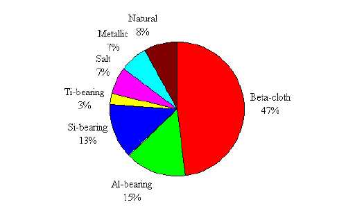
Figure 19: Chemical analyses synthesised into broad groupings.
Table 5
| Description | Number | % of Total |
| Beta-cloth | 36 | 42.9 |
| Al-bearing | 11 | 13.1 |
| Si-bearing | 10 | 11.9 |
| Ti-bearing | 2 | 2.4 |
| Salt | 9 | 10.7 |
| Metallic | 10 | 11.9 |
| Natural | 6 | 7.1 |
| TOTAL | 84 | 100.0 |
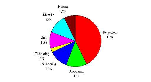
Figure 20: Chemical analysis assuming the occurrence of composite particles.
Note, however, that if analysis of all particles on each layer was undertaken, then the total percentage of beta-cloth pieces would be much higher, since the search undertaken actively tended to avoid particles which had the characteristic ÒwhiskeryÓ morphology of beta-cloth fragments. Thus the data have been re-normalised on a Òbeta-cloth-freeÓ basis:
Table 6
| Description | Number | % | Origin |
| Al-bearing | 11 | 22.9 | Rocket propellant |
| Si-bearing | 10 | 20.8 | Electronic compts., paint, silicone grease |
| Ti-bearing | 2 | 4.2 | Paint |
| Salt | 9 | 18.8 | Astronaut waste |
| Metallic | 10 | 20.8 | Electronic compts., spacecraft materials |
| Natural | 6 | 12.5 | Micrometeoroids |
| TOTAL | 48 | 100.0 |
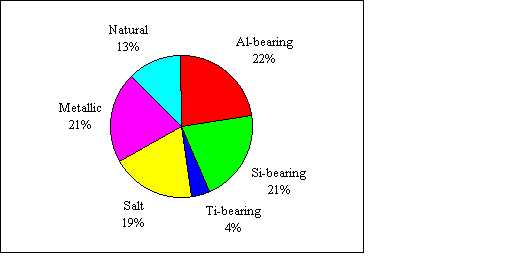
Figure 21: Chemical analysis of particles and residual material, excluding beta-cloth data.
Table 6 shows that Al-bearing, Si-bearing, salt and metallic particles make up, in each case, about 20% of the total. All of these materials are presumed to be space debris. A further 4% is from Ti-bearing particles, which are most likely from paint fragments. The natural samples comprise about 12% of the analyses. This distribution cannot be directly related to impacting flux, because particles of different types were found in individual holes, and some of the analyses are weighted because of multiple measurements (i.e. the same particle type detected more than once within an individual impact). In an attempt to synthesise all the data to determine the distribution of impactor types, Table 7 and Figure 22 have been constructed, in which the assignments are made on a per-hole basis.
Table 7
| Description | Number | % of Total |
| Unknown | 34 | 57.6 |
| Space Debris | 20 | 33.9 |
| Natural | 5 | 8.5 |
| Total | 59 | 100.0 |
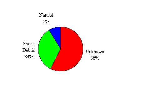
Figure 22: Summary of impact types (for 59 separate events).
Thus, it would seem that of the 59 holes, 33.9% were definitely made by space debris and 8.5% by natural micrometeoroids. The nature of the particles that created the other 57.6% remains unknown.
6.5. Analysis of Surface-Sited Particles
For the surface-sited particles, the MLI blankets were not delaminated; the samples were carbon-coated and analyses made in situ. Three particles were studied in detail (Section 4.2.1 and Figure 4), since they appeared to be fused into the beta-cloth and thus might represent impacts rather than contaminants. The three samples were 125 Core B, 125 Core D and 252.1; the results are included in Appendix A4. Also shown in Appendix A4 are assessments of the likely nature of the other components based on optical examination. Some familiar properties came to light during analysis of the surface-sited particles, suggesting that each event was the result of the impact of a space debris particle (i.e., zinc-bearing, zinc-chlorine-bearing and pure iron). Similar particle type were also seen within (different) samples of MLI as discussed in the previous section. That the particles have not penetrated the beta-cloth should constrain their impact velocity - clearly this must have been quite low.
Sample 106.1b is an interesting, and unique, case. There appears to be an impact depression within the beta-cloth, but there is no penetration and no particles are present on the surface. It is likely that this was caused by the low-velocity impact of a particle that has subsequently been lost. If the impactor evaporated completely upon impact, it must have been highly volatile. Alternatively, if the particle were only lightly fused onto the beta-cloth, it may have become dislodged during recovery of the spacecraft, during deintegration, or sample handling.
The other surface-sited components are considered to be contaminants added at some point during spacecraft recovery or deintegration (but in any case, before the preliminary optical survey). The particles are loosely attached to the surface of the beta-cloth and appear to be easily removable. All of these samples have been curated under standard conditions, and could be made available for further research if required.
7. Conclusions
The main findings of this project can be summarised as follows:
- Impact events are readily detected in the MLI blankets from EURECA.
- The holes range in size from a mean diameter of ~ 60mm to ~ 1200mm. Most holes are generally ellipsoidal in shape, implying oblique impact by the particles.
- The distribution of hole sizes is approximately bimodal, with maxima at 250 - 350 mm (n = 20; 32%) and 400 - 500 mm (n = 11; ~ 18%).
- The cumulative impact flux distribution (although not corrected for impact substrate) is similar to that determined for LDEF.
- In Type 6 MLI, there is a positive correlation between the size of the impact hole into the top, beta-cloth, surface, and the number of layers subsequently penetrated. This observation is consistent with the largest holes being made by the particles with the highest energy (either due to high mass or velocity).
- Beta-cloth contains the same major elements (Si, Al and Ca) as many natural micrometeoroids, thus MLI surfaces are not a good medium for the effective capture of natural samples for subsequent study.
- Particles were readily detected within most blankets. Individual penetration features often contained many particles, and these might be of different chemical compositions. The particles were not always close to the impact feature itself.
- Chemical analysis of particles associated with impact holes indicated that ~ 7% were natural micrometeoroids, and 43% were pieces of beta-cloth carried into the interior of the blankets as a result of the impact. The remaining particles are space debris of some form.
- Normalising the chemical analyses to a Òper holeÓ basis, ~ 8% of the features were produced by natural micrometeoroids and ~ 34% by space debris. The remaining 58% of the holes cannot be assigned a specific origin.
8. Acknowledgements
The Photography Section of the Natural History Museum is gratefully acknowledged for helpful advice and information. Many thanks are also due to Dr. Bill Carey of SAS, Belgium and Drs. Tim Stevenson and Sunil Deshpande (Mare Crisium) for their encouragement and expertise.
9. References
- Aceti, R., Drolshagen, G., McDonnell, J. A. M. and Stevenson, T. (1994). Micrometeoroids and space debris - the Eureca post-flight analysis. ESA Bulletin, 80, 21-26.
- Berthoud, L. (1995). EURECA Thermal blanket investigation. ESTEC Working Paper, 1825, 23 pp.
- Brownlee, D. E., Hörz, F., Hrubsch, L., McDonnell, Tsou, P. and Williams, J. (1994). Eureka! Aerogel capture of meteoroids in space. Lunar and Planetary Science, XXV, 183-4.
- Grady, M. M., Sexton, A. and Wright, I. P. (1995a). Morphology and chemical analysis of residues from impacts into MLI-blankets on EURECA. Lunar and Planetary Science, XXVI, 485-6.
- Grady, M. M., Sexton, A. and Wright, I. P. (1995b). Impacts into MLI-blankets on EURECA. Annales Geophysicae, Suppl. III, Vol. 13, C737.
- Aeritalia Space Systems Group (1989). EURECA flight thermal analysis report. EC-RP-AI-058, Issue 01.
- McDonnell, J. A. M. (1994). EURECA's hypervelocity impact score: microcrater flux decreases but the large crater flux increases in specific directions. Lunar and Planetary Science, XXV, 867.
- McDonnell, J. A. M. and Stevenson, T. J. (1991). Hypervelocity impact microfoil perforations in the LEO space environment (LDEF, MAP AO 023 experiment). In: LDEF - 69 Months in Space.
- First Post-Retrieval Symposium. (ed. A. S. Levine), 443-458. UniSpace Kent, Space Application Services and T & M Engineering. (1994). EuReCa micrometeoroid and debris post flight investigation. Final Report and Technical Report, Contract No. 10335/93/NL/JG.
- Zolensky, M. E., Zook, H. A., Hörz, F., Atkinson, D. R., Coombs, C. R., Watts, A. J., Dardano, C. B., See, T. H., Simon, C. G. and Kinard, W. H. (1993). Interim report of the meteoroid and debris special investigation group. In: LDEF - 69 Months in Space. Second Post-Retrieval Symposium. (ed. A. S. Levine), 277-302.